| I was asked to do a writeup for my alarm install. I originally wasnt going to but had some free time, so here it is. --------------------------------------------------------------------------
This install was for a Viper 5901 alarm into a 92 300ZX N/A MT.
Procedures to follow: Roll a window down to avoid locking your keys in your car.
It is advisable to disconnect the battery before working on any electrical components.
Always keep an automotive or electrical grade fire extinguisher close by.
Solder all connections and insulate with heat shrink tubing.
Even if you only have to splice the wire, cut it and solder with heat shrink tubing on it.
Stagger connections to further limit possible shorts.
Some of the pictures and procedure were copied from Jodecy (With permission).
For starters, I found three sites that had wiring guides. Unfortunately none of the three were entirely complete or correct. So I used them and my multimeter to create my own table.
| Function |
Color |
Polarity |
Location |
| 12V Constant | White/Red | + | Ignition Harness |
| Ignition 1 | Black/White | + | Ignition Harness |
| Ignition 2 | N/A | N/A | N/A |
| Starter | Black/Yellow | + | Ignition Harness |
| Starter 2 | Black/Green | + | Ignition Harness |
| Accessory | Blue | + | Ignition Harness |
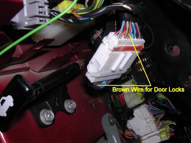
| Power Lock | Brown | *1 | *1 |
| Power Unlock | Brown | *1 | *1 |
| Parking Lights | Green/Red | + | Light Switch Pod |
| Door Trigger | Blue | - | Anti-Theft Module |
| Trunk Pin | Blue (common to doors) | - | Anti-Theft Module |
| Hood Pin | Orange/Blue | - | Anti-Theft Module |
| Factory Alarm Arm | Blue/Red | - | Drivers Kick Panel |
| Factory Alarm Disarm | Grey/Red | - | Drivers Kick Panel |
| Tach Signal | Yellow/Red | A.C. | ECU |
| Brake Wire | Red/Black | + | Brake Pedal Switch |
| Parking Brake Wire | Yellow/Pink | - | Center Console |
| Horn Trigger | Green/White | - | Steering Column |
| Neutral Safety | Yellow/Blue | - | ECU Pin 44 |
*1 Refer to Graphic below.
* Ignition Harness Wire colors are noted for the key side of the plug. As always, mistakes and malpractice are not my fault and not my responsibility. ALWAYS solder the connections (properly) and use quality heat shrink tubing. Moving On... What I installed in my car is as follows: -Viper 5901 Alarm
-DEI 520T Backup Battery
-DEI 508D Dual Zone Motion Detector
-507M Digital Tilt Sensor
-DEI 506T Audio Glass Break Sensor
-DEI 522T Trunk Release Solenoid
-Second Shock Sensor
I have had the alarm fully functioning for about a day. I am impressed with all of it except for the 2-Way remote, response is a bit lagging compared to the 1-way (also included). I had to bypass the neutral safety because my switch is bad (and a replacement is on its way). The bypass was temporary just to test the function, and is now removed.
First thing I did was to locate where the main control center would be located. Following Jodecy I figured the space between the glove box and the radio would do. Later I had to modify this to the spot under/below the radio as the 5901 has an on board shock sensor and remote start relay, making this box too big to fit. Next was to pick a suitable location for the receiver. I chose to mount it in the roof (to be as high as possible). I removed the passenger side T-top, a-pillar mount, a-pillar, and roofing trim. I ran the wire through the location and slid the receiver into position. The center of the rear of the ceiling trim had plenty of clearance. --Note, if you mount this here you will NEED an additional separate valet switch. Separate LED is optional.
From here I laid out all the wires and noted what position each one needed to take (minus the remote start harness).
When this was done I put the wires in the car in the same format. I ran the wires to the left on the crossbar and above the steering column (obviously). This was the easiest routing that avoided most of the sharp edges. For the wires that went right I used a coat hanger and pulled the wires through above all the AC venting on the passenger side. Center wires I ran down the center column and zip tied together as not to get confused later. I starter on the right with what I knew, and worked my way to the left.
Right Side:
Wires to the right: -Siren Output
-Trunk Release Output
-Door Trigger Input
-Trunk Pin Instant Trigger Input
-Aux 2 Out (unused, for later)
-Aux 3 Out (unused, for later)
-Neutral Safety Switch Input
-Tach Input
-Hood Pin Wire
-Factory Arm/Disarm (If you have factory alarm) I started on the right side as it was easier. To get to the components you will need to remove the ECU cover board, the ecu, and the anti theft module. The anti-theft module is mounted up high and way out of sight (for security of course). It’s above and outboard of the ECU. Two bolts and a bit of maneuvering gets it out. The wires are a bit tight but connecting the BLUE door trigger wire and Orange/Blue hood trigger weren’t hard. 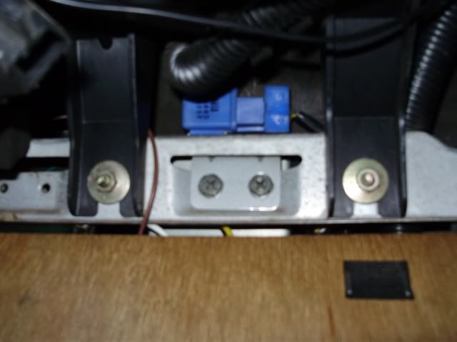
The blue relay is attached to the anti-theft module, the two bolts below it hold the whole setup in. 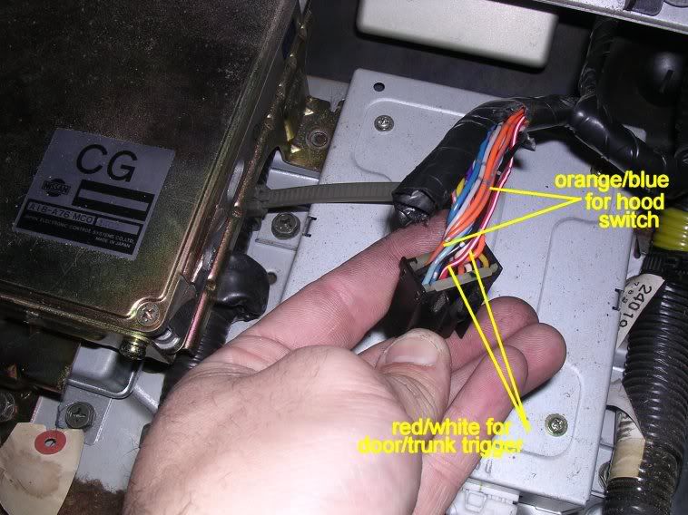
The thought ran past my mind to diode isolate the trunk hatch switch so that the LCD remote would tell me the trunk was open instead of an open door code. Instead I just used the trunk trigger for one of my extra sensors. To do this you would just wire it as follows: 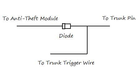
The Tach signal wire goes to the ECU pin 7. This is a Yellow/Red wire.
(Manuals) While you have the ECU socket off, take the time to hook up the Neutral Safety Switch wire to Pin 44 (Yellow/Blue). This pin shows ground when the car is in neutral and is essential to safely remote starting your car. (ECU Diagram)
For Automatics, the neutral wire will be coming off the shifter mechanism. I am unsure of the color, it can be tested as the wire that shows ground when in Park and Neutral Gears. Have the parking lights on when you do this so you don’t tap into any lighting wires or the brake lock wire.
I ran the trunk release wire above the AC vents to the kick panel. The 522T Includes a long wire for activating the solenoid, but the control module can’t handle this much current.
To connect this you must use a relay as follows. 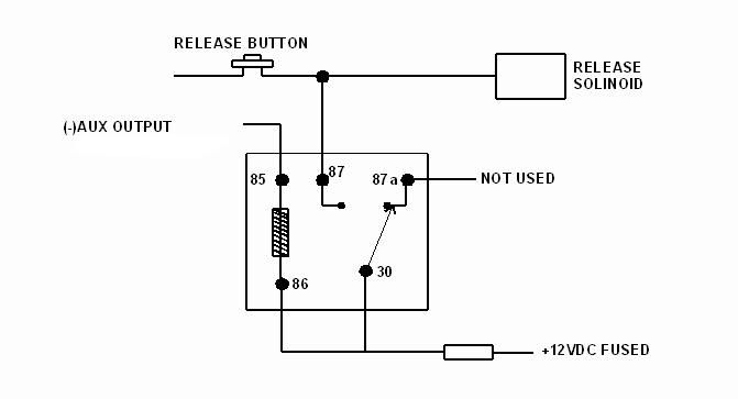
I mounted the siren (I used a power steering bolt location, but will move it later) and ran the wires through the grommet in the passenger side fender well.
The Aux 2 and 3 wires are zip tied so they don’t get in the way. Later I plan to use Aux 2 to turn on underbody lights (possible engine bay lights also) with the remote. I have a wild dream of using Aux 3 to automate and open my doors with a vertical doors kit, with the remote. Still looking into that ability.
Left Side:
Wires to the Left:
- +12V Constant (H1/2, Red)
-Parking Light Output (H1/11, White)
-Ground When armed (for window automation system, H1/12, Orange))
-Aux 1 Output (For window module)
-Horn Honk Output (H2/8, Brown/Black)
-Brake Shutdown Wire (Remote Start Input, Brown)
-Door Lock Harness (3 Pin Connector)
-Status Output (Remote Start Auxiliary, Blue)
You will need to remove the knee plate, the driver side vent panel, and the two AC ducts.
I tied the +12V Constant wire up to keep it out of the way and to avoid soldering the wire multiple times when I install the remote start harness. If you are using a backup battery wire, leave this wire in the center of the console, and instead run the backup battery’s +12V wire instead.
Running the parking light wire takes some finesse. I hadn’t pulled out the coat hanger yet so this was a little more work for me, easily avoided. Two screws on the bottom hold the light pod in, remove these two screws and pull the bottom out, gently push the top hooks down and out. Snake the parking light wire up there and solder it to the green/red parking light wire. 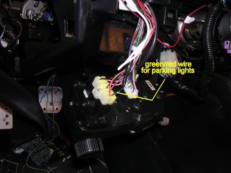
The green/white wire on the steering column controls the horn. The viper 5901 is set to the factory where the horn will only honk during full alarm, which is how I wanted it. Carefully Splice in to it. The Brake switch wire is tucked way up underneath the dash. Lying on my back I was able to (barely) reach up underneath the dash and after finding out which one had the red/black wire, disconnect the proper plug. Couldn’t get a clear picture of this though. While I was at it, I disconnected the forward clutch plug. I used a relay and the alarms "Status Output" to wire in a clutch bypass ONLY when the alarm is remote starting the car, and AFTER verifying both the Parking brake is active and the car is in neutral. This is for SAFETY purposes. It doesn’t matter which of the clutch sensor wires you put in which position as it forms a loop. Wiring Diagram for clutch Bypass: 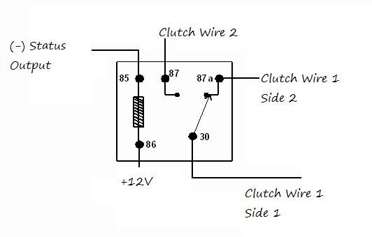
What this does is, when the system is preparing to remote start, the relay completes the circuit, telling the car that the clutch is being pressed (although it isn’t). When there is no signal, the wires act as if the relay didn’t exist. This is only to be used when the neutral safety switch and parking brake are correctly hooked up. As for door locks, there are options. I was unaware that the 92+ had motors in both doors, so I installed my own actuator. If you have a 90-91 You have to add an actuator and follow this diagram (provided by the12volt.com) 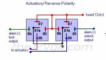
You will have to experiment with the wiring to your actuator. Originally I hooked up the blue wire of my actuator to the relay that had the blue wire input from my alarm. When I first tried it (with the keys in the car) I hit the lock button, no dice. So I hit unlock to which the alarm disarmed. Only problem was the polarity was reversed. On unlock my doors locked, and the ground wire for the 'lock' (which unlocked) relay was left disconnected. Hence the roll your window down precursor. If you have a 92+ and wish to use the stock actuators, follow the diagram from Jodecy as follows: 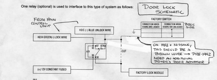
Middle:
The wires that were needed in the middle were: -Chassis Ground (H1/5, Black)
-Remote Start/Turbo Timer Activation (H1/10, White/Blue)
-Trunk Pin (If being used for sensors instead of diode trunk switch)
-Wiring For Optional Sensors -Placement of sensors.
I don’t think a write-up on how to ground the system is necessary... I used the ground point to the back left of the radio cubby.
The White/Blue wire is used to activate the turbo timer built into the 5901. The downfall is that it can only be set to 1, 3, or 5 minutes. I wired this to the yellow/pink parking brake (-) wire. 
From the manufacturer this is set to one pulse, meaning from driving, when you pull up on the parking brake the turbo timer will activate. This has a minor problem because this wire also activates the remote start... Pulling the brake while the car is off will start the car (if in neutral as determined by the neutral safety). You can set this to two pulses to avoid this. I also took this time to place all the sensors. I bought industrial sticky Velcro strips to mount all the sensors. Backup battery went to the position between the radio mount and the glove box (along with its sensor), tilt sensor is small and on the flat spot next to the shifter, separate valet switch and radar sensor go as Jodecy placed them, and the second shock sensor went to the dash cross link above the drivers kick panel. 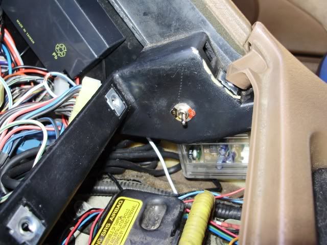
(Ignore the stereo wires) I figured this was the most logical place for the second shock sensor because the majority of vandalism and theft will come from the driver’s side. 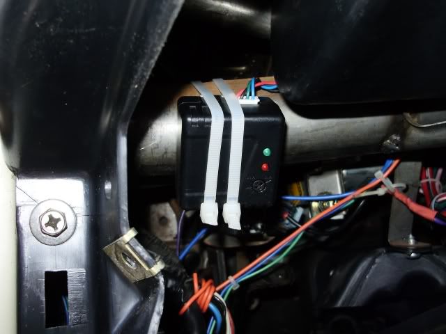
You can also see the orange ‘ground when armed’ wire that I will later use for the window automation module. Tilt Sensor (Double sided sticky tape) 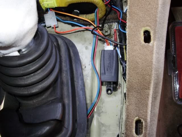
The proximity sensor is mounted in the place recommended by Jodecy. 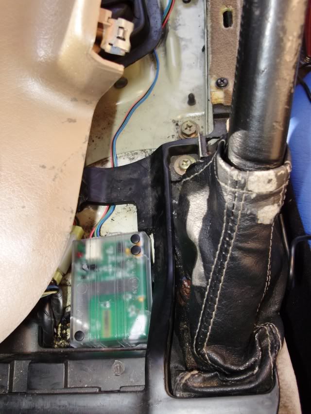
Now its time to tackle the uber confusing remote start harness.
You will need to remove the tray hiding these wires and unplug the connector. 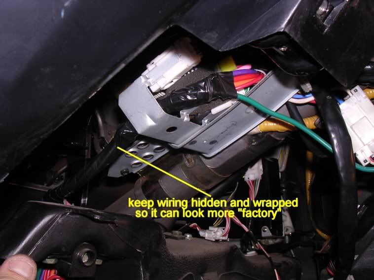
It is up to you which side you want to solder on, the colors listed are for the key side. I chose to solder on this side because I figured the key cylinder was easier to replace than the wiring harness of the car. 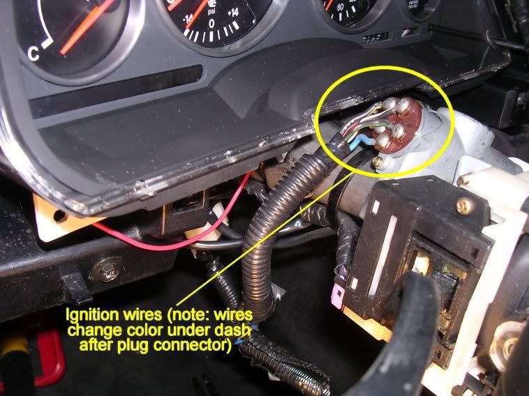
I installed a 791XV alarm remote start with no problems, and I don’t see why they couldn’t have made this one just as simple. Anyhow, the wiring will be left up to you, but the connections are as follows: Note, a wire that says key/car side means the wire is cut and separated, lacking that designation means it is spliced. (Just for clarity) H3: Heavy Gauge Remote Start Harness H3/1 - Pink - Ignition 1
H3/2 - Red/White - Ignition 2 Input
H3/3 - Orange - Accessory
H3/4 - Violet - Starter Output
H3/5 - Green - Starter Input
H3/6 - Red - Ignition 1 Polarity Input
H3/7 - Pink/White - Flex Relay Output
H3/8 - Pink/Black - Flex Relay 87a
H3/9 - Red/Black - Acc/Starter Polarity In
Although this is confusing and took me awhile to figure out, the outcome is to wire it in the form:
Pink - Black/White (Ignition)
Red/White - White/Red (+12V)
Orange - Blue (Accessory)
Violet - Black/Yellow Car Side (Starter)
Green - Black/Yellow Key Side (Starter)
Red - White/Red (+12V)
Pink/White - Black/Green Car Side (Starter 2)
Pink/Black - Black/Green Key Side (Starter 2)
Red/Black - White/Red (+12V)
Don’t be confused when the car doesn’t start when you immediately try it. You must program the flex relay to be a Starter 2 Setup. Manufacturer Programming has it set as Ignition 2.
Don’t start putting the car back together just yet.
First things first, make sure your car starts. When I tried I realized I had put the ignition wiring tray back in without plugging it in, so my car was dead. After plugging it in everything went fine (minus the not remote starting that I had to troubleshoot). Check the function of all the sensors, make adjustments as necessary. For the tilt sensor, I chose to cut the sensitivity wire, but leave the alarm wire on. 3 degrees is a much more suitable activation limit to prevent false alarms. Adjusting the dual zone radar sensor, you need to adjust the outer ring (which adjusts both) to your wants, and then adjust the inner zone to go off only when something enters the boundary of your interior (as to not annoy). The on board impact sensor can be adjusted through the remote. Once you have verified everything is working, assemble the car again, and you’re done. Thanks to Jodecy for letting me use his pictures. His writeup can be found HERE.
|


 Viper 5901 Alarm/Remote Start Installation Procedure -