| An all too familiar scenario, the rear end starts to get
a little unstuck, the driver doesn't catch it in time, and that's it, 3500+
lbs. of metal, plastic, and leather heading towards the scenery. Nissan
has put a nice powerful road car in the hands of the general public, the
likes of SGP, JWT, NISMO etc. have given the general public the ability
to make an already quick car even quicker, unfortunately the skill required
to back up that power and handling is not there, and even if the skill
was there, often things just happen on the road people have no control
over. "You're only as good of a driver as you thought you were until the
rear end gets away from you"
What is the Racelogic Traction Control? A way of controlling excess
power (or even just "normal" power in slippery conditions, IE ice, snow),
without detracting from performance, or the driving experience (in fact
I firmly believe that TCS adds to the driver experience). Conventional
driving skill in a rear wheel drive car in over steer situations is to
feather the throttle (lift-press-lift-press) as the rear end goes into
over steer. Lifting off the throttle completely transfers the vehicles
weight onto the front wheels unbalancing the car, or giving too much throttle
decreases grip as the wheels spin even more, either method results in a
trip to the scenery (at best, at worst potentially a lost life). The TCS
system feathers the throttle automatically, without closing the throttle
(in a turbo car causing the engine to come off boost), or using the braking
system. It interfaces with the ABS system to "read" the wheel speeds (and
calculate the wheel slip on all 4 corners), and interfaces with the ECU
harness to cut engine power by cutting fuel.
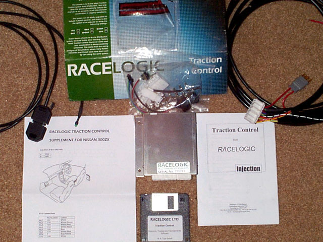
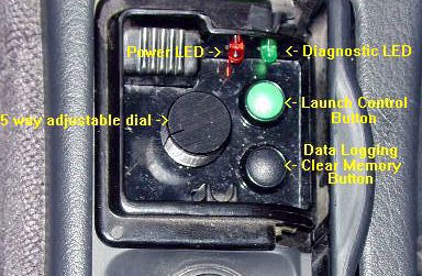
The two additional modules I purchased were the launch control and adjustable
slip controls.
I would whole heartedly recommend the adjustable slip module, which
gives you the "adjustable fun dial" as I call it. Basically you can select
the desired amount of wheel spin on the dial 0%-5%-10%-15%-20%-OFF.. at
0% the rear end will not go into oversteer, 10% and you've got a bit of
oversteer going on, 20% is for serious showboating!.
Launch control allows you to do perfect launches whenever you want -
it lets you build boost on the line, drop the clutch, maintain wheel spin
and generate max acceleration off the line (perfect for those 60ft times!)
. Whilst stationary you select the wet or dry launch (dry has a hard cut
limit vs the wet soft cut limit, IE the dry will build more boost), press
the launch control button, floor the throttle - the engine "bounces" off
a secondary rev limiter controlled by the Racelogic system - in fact it
sounds like a Rally Car on the start line. Once max boost is generated
(around 5-7psi in Stg 3 car @ 5500rpm limiter), you let go of the clutch.
The system modulates engine power to control wheel spin - gradually feeding
in engine power until full power is unleashed and then it's time for 2nd
gear! The launch is absolutely incredible, but a side effect is you have
to have a good clutch, otherwise this will ruin the clutch quickly.
Speed shift allows you to leave the gas pedal on the floor while making
shifts. When the clutch is pushed in, a new rev limit is imposed on the
engine so the engine won't over-rev when the drivetrain is disengaged from
it. Coupled with the launch control, it can make a standard perform like
an automatic for acceleration.
I won't go into the technical details of how it works (go to www.racelogic.co.uk)
other than answering four of the most common questions/comments:
1. If it cuts fuel, doesn't that mean it will detonate? An emphatic
NO, what it does is cut enough fuel to create a complete misfire on one
injector pulse, cycling around all the cylinders. Enough fuel is cut out
so a complete combustion won't occur, but not too much fuel so that the
cylinder won't dry out.
2. I've been in production cars with Traction Control, they were more
of a detriment, how come this one is so different? The Racelogic system
is race derived, and adjusted to each application. It has an extremely
quick sample rate, and is fully adjustable in how much fuel it cuts out,
which revolutions the fuel is cut, which cylinders etc etc all settings
are accessible via a PC connection. The system only cuts just enough power
to limit or eliminate wheel spin, but not so much to degrade performance.
Many production systems are too slow at reacting and cause the engine to
drop power dramatically when they kick in.
3. But I'm a good driver, I don't need it! No human can modulate engine
power without using the throttle, so even if you were Michael Schumacher,
you still wouldn't be able to control power delivery without closing the
throttle, and doing it 10 times / sec. There is a reason why lots of racers
choose to install race spec traction control systems, as it offers the
ability to bury the throttle and get the maximum amount of power delivery
without having to modulate the throttle as the rear end starts to get unstuck.
4. So, what's it like? Full throttle, 2nd gear, in a stage 3 car on
super grippy 17" tires partway through a corner, in the wet, and not having
the rear end go into oversteer sets the stage for how well this system
works. I simply could not believe the night and day difference in character
of my TTZ in both wet and dry conditions. In the wet it changes the car
from being on the thin line, to completely in control, in the dry it allows
me to get on the throttle earlier, and hold the throttle down in a corner.
You get to a point where you jump on the throttle immediately after turn
in, and only lift if you're understeering. It's an eerie sensation, especially
if you're "used" to driving a rear wheel drive car, but after a while you
get totally comfortable with the system. I asked Racelogic "Would I know
when it starts cutting power?" "You will".. and you do, the engine sounds
like it's missing, but not badly. Hard to describe, but it cuts in and
creates a repeated misfire that sounds very "race-car-ish".
Strongly recommended for anyone, be it Drag Racers, Road Racers or Sunday
drivers.
Rowan Hick, Sonic-Motorsport.com
Basic tools needed:
soldering iron and solder (or crimping tool and non insulated 20-22
gauge crimps)
wire cutters/stripper
10 mm socket
flathead and #2 phillips screwdrivers
electric tape/heat shrink tubing
multimeter (optional, but highly recommended)
double sided tape or velcro
utility knife
drill
IMPORTANT NOTES... READ FIRST!
This is a relatively easy installation. If you know how to use a screwdriver
and can solder or crimp 2 wires together, you can install this unit. These
instructions are very long, but that's only because I was very detailed
about the simplest things (like how to splice, etc.). so, don't be scared
by the length. Read through the instructions in its entirety before starting.
It should take 2-4 hours to finish the installation
Take your time and make sure all your electrical connections have good
continuity after each soldering joint by using your multimeter (set on
resistance) with the probes on either side of the solder joint (i.e. one
probe at the pin of the harness connector and the other about an inch past
the solder joint).
Wires which are multi-colored are denoted as follows: "main color/stripe",
such that "white/green" means a white wire with a green stripe.
The pin number of a specific wire is indicated in parentheses after
the color wire. For example, white/green (8) means the white wire with
a green stripe that is connected to pin number 8 of the harness connector.
Be sure to cover all exposed wires with electrical tape or heat shrink
after soldering/crimping.
Abbreviations used: ECU = electronic control unit (the brains of the
car), ABS = anti lock braking system.
1. Use a deep 10 mm socket or wrench to disconnect the negative (-)
terminal of the battery (the black cable).
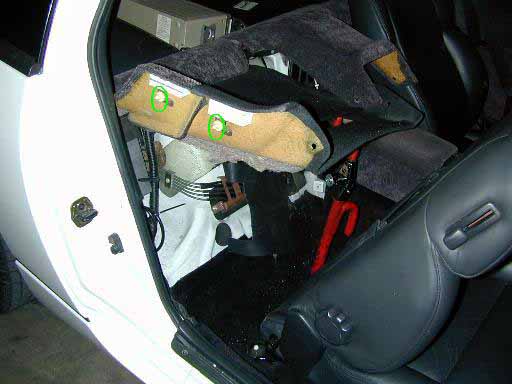
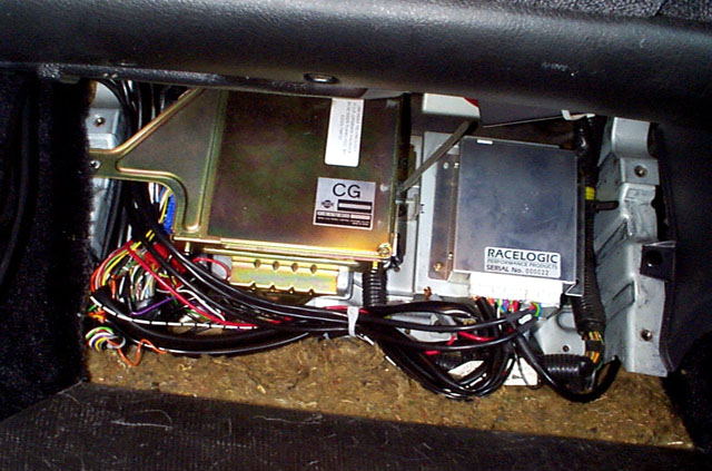
2. Access the ECU which is located under the passenger floorboard by
removing the floor mat, pulling back the top part of the carpet, unscrewing
the four 10 mm bolts that hold the wooden panel, and removing the wooden
panel. For more detailed instructions and pics, see the FAQ for instructions
on running an ECU
diagnostic.
3. Disconnect the ECU by unscrewing the three 10 mm bolts that hold
it in place. Then, remove the harness from the ECU by unscrewing the 10
mm bolt in the middle of the blue connector and pulling the connector out
from the ECU.
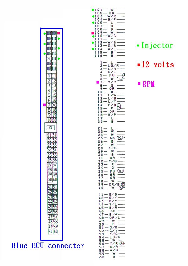
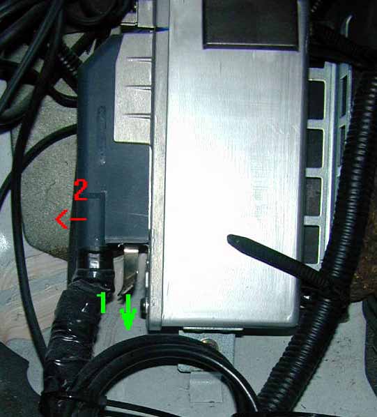
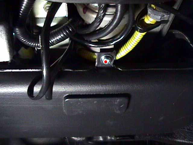
4. Cut away some of the black insulation around the Racelogic unit harness
wires and locate the 6 fuel injector wires (green dots in 2.) on
the ECU harness.
5. Use the multimeter set on "resistance" to make sure it's the right
wires. Put one probe into the ECU connector and the other on the cut wire.
If you have zero ohms showing (means that there is continuity), then it
is the correct wire.
6. Cut the fuel injector wires and connect the Racelogic wires to either
end. The wires may be connected in one of three ways: solder them, crimp
them, or use the included male/female pins and plastic connectors to make
your own connectors. If opting for the third option, make sure to have
the proper crimp tool ($5-10 from Radio Shack). Making a connector is convenient
if the Racelogic unit has to be taken out (that way, just snap the injector
wires back together), but it is more time consuming and easier to mess
up if the right crimp tool isn't used. Make sure to put a female connector
and a male connector on the injector wires and the correct ones on the
Racelogic harness! Connect the following 12 wires together, These are the
ones going from the ECU to the Racelogic unit.
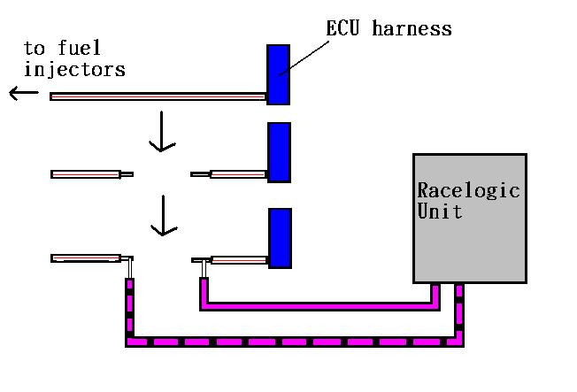
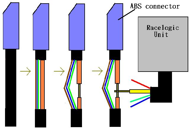
NOTE: Do NOT splice the Racelogic wires into the intact fuel injector
wire. They must be CUT. By connecting the Racelogic wires to either end,
it allows the signal to go from the ECU to the Racelogic unit, and then
from the Racelogic unit to the injectors (3.). Thus, the Racelogic
unit essentially "intercepts" the ECU signals before they go to the injectors.
Wire from ECU (pin#) TO wire going to Racelogic unit
Inj.1 white (101) TO red
Inj.2 white/green (110) TO orange
Inj.3 white/red (103) TO gray
Inj.4 white/black (112) TO green
Inj.5 blue (105) TO yellow
Inj.6 white/blue (114) TO pink
Connect the following 12 wires together. These are the ones going from
the Racelogic unit
to the fuel injectors.
Wire from Racelogic unit TO wire to fuel injector
Inj.1 red/black TO white
Inj.2 orange/black TO white/green
Inj.3 gray/black TO white/red
Inj.4 green/black TO white/black
Inj.5 yellow/black TO blue
Inj.6 pink/black TO white/blue
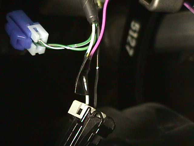
7. Splice the black/white Racelogic wire into the yellow/red tach pulse
(pink dot in 2.) ECU harness wire by removing a little bit of insulation
from the yellow/red wire to expose bare wire and solder the black/white
wire to it.
NOTE: This is splicing into the INTACT wire� NOT cutting it in two like
the injector wires.
8. Splice the red Racelogic wire into the white (red dot in 2.)
ECU wire (red square in wiring diagram above). Again, do NOT cut the white
wire, just remove some insulation and connect the Racelogic wire to the
bare wire.
9. Bolt the double black Racelogic harness wire with the ring terminal
to a suitable ground. I found a few nuts above and to the right of the
ECU that I simply undid, slipped the ring terminal over, and tightened
the nut over it. Do NOT try to attach the ground to a painted area.
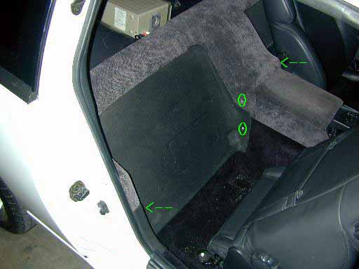
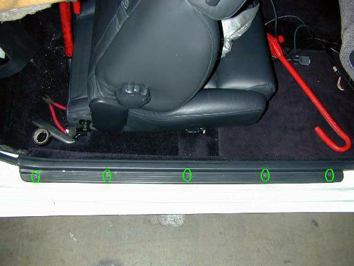
10. Locate the ABS unit, it's behind the passenger seat. To access it,
unscrew the two phillips screws that are on the center console (green circles
in 4.), also unscrew the two with little black covers that can be
flipped up with the flathead screwdriver (green arrows in 4.). Prop
up the center section and remove the last screws underneath (green circles
in 5.). Pop out the two plastic grommets (green circles in 6.)
on the left side of the panel and prop the panel up. I used my CLUB anti-theft
device to prop up mine.
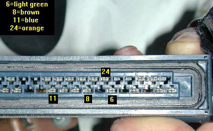
11. Remove the ABS harness connector and splice in sensor wires. In
order to remove the blue connector, pull down on the metal tab on the bottom
and pull the bottom of the connector out (7.). Carefully cut away
some of the black insulation about an inch or two from the blue plastic
connector. Locate the following wires which connect to the ABS connector
(again, it's best to use a multimeter to make sure it's the right wire
going to the right pin):
Splice in the Racelogic wires as per the diagram below, do NOT cut the
ABS wires in two.
Racelogic Wire TO ABS wire
red TO brown (8)
blue TO blue (l for lavender in the service manual) (11) (23 on at
least 95's see note below)
yellow TO orange (24)
green TO light green (6)
NOTE: There are 2 identical brown wires in this harness, one goes to
pin 1, the other goes to pin 8. Make certain the brown wire tapped into
is the correct one.
NOTE: the blue wire on the '95 connector is in slightly different location,
see listing above. I think this change is due to the new style ABS actuator
on '94+ models.
12. Route the ABS wires back to the ECU area. The easiest place to put
the wires from the Racelogic unit is in the door sill. Simply unscrew the
phillips screws (green circles in 10.) and stuff the wires beneath
the black plastic panel. Be sure to keep the wires away from sources that
may cause interference. For example, if there's a 12,000 gigawatt stereo
system involved, do not place the Racelogic wires on top of the speaker
wires. The electrical impulses traveling through the speaker wires (not
line level cabling, but speaker level wires) may induce false signals in
the Racelogic wires. The Racelogic wires are shielded, so it's unlikely
to happen, but it's better safe then sorry.
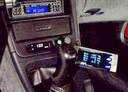
13. Mount the controls. This is a matter of personal taste, but Orion
and I wanted to show you where we mounted our stuff. Orion mounted the
launch control and adjustable dial next to the clock (11.). I put
mine in the ashtray for a "stealth" look (12.), so when the ashtray
is closed, the controls aren't visible.
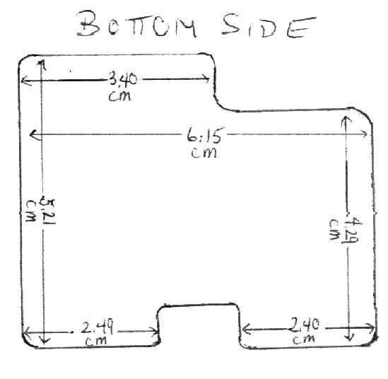
14. To make the panel for the ashtray, I simply got a piece of Plexiglas
from Home Depot, cut it out according to the template (13.) with
a Dremel tool, spray painted the bottom (so it looks shiny from the top),
and
mounted the dials/switches. For the laptop connector, I threaded it
up through the glove box so that when I
need to connect my laptop, I just pop open the glove box and pull it
out.
15. Connect and mount the Racelogic unit. Plug all of the white connectors
into the Racelogic unit. There's a nice space next to the ECU where the
unit can be taped/velcroed in place (14.).
16. Calibrate and adjust settings. Calibration is explained very well
by the instruction manual. I'll just add be sure to drive at a speed that
will allow for NO wheel spin while calibrating, otherwise it'll confuse
the unit. Make SURE the following are set correctly before taking it out
on the road. Follow the instructions for connecting a PC to the control
unit using the built in serial cable. Use Procomm (provided with the unit),
turn the key to the ACC ON position... this will turn on the traction control
unit and Procomm will show a prompt on the screen (something like "VTRAC6").
MAKE SURE YOUR CAP LOCK IS ON!!!
Press E to bring up the main menu. Press W to bring up the Speed Sensor
Configuration menu. Set the following in this menu. N. and M. - 00046 (these
are the # of teeth per revolution on the ABS sensors). T. and U., wheel
diameters (calculate these off of your tire size). The "driven wheels"
are the rear wheels and the "reference wheels" are the front wheels. To
calculate, use the following formula...
(width x profile / 50) + (wheel diameter x 25.4)
This will give your tire size in millimeters. Such that for the stock
245/45/16 rear tires, you will get the following...
(245 x 45 / 50) + (16 x 25.4) = 627 mm (so enter 00627 for driven
wheel diameter)
and for the stock 225/50/16 front tires, you will get...
(225 x 50 / 50) + (16 x 25.4) = 631 mm (so enter 00631 for reference
wheel diameter)
NOTE: Do NOT measure the tire/wheel diameter with a ruler. This is VERY
inaccurate and will throw off the traction control unit. If there are problems
do the calculation, please e-mail me with the tire sizes and I'll do them
for you.
Calibration steps can be skipped if the wiring was done correctly above.
Calibration just tells the unit which sensors are on which wheels. Simply
input the following:
1 - OFF
2 - ON
3 - OFF
4 - ON
This tells the unit that 1 and 3 are the rear wheels and 2 and 4 are
the front wheels (because OFF = driven and ON = reference).
A - OFF
B - ON
C - ON
D - OFF
This tells the unit that A and D are the right wheels and B and C are
the left wheels.
Hit esc to go back to the main menu. Under C. - configuration menu,
make sure that "C", the number of cylinders is "00006".
The amount of traction control you'll want will depend on the power
output of your engine. The default settings are fine for about 400-450
crank hp. Once higher than that, a few settings will have to be tweaked.
More traction control can be dialed in by changing the slip percentages
to lower numbers. For maximum straight-line acceleration, 8-10% wheel spin
is optimal. If that still isn't enough to control all of the spin, play
around with the fuel cut tables to adjust.
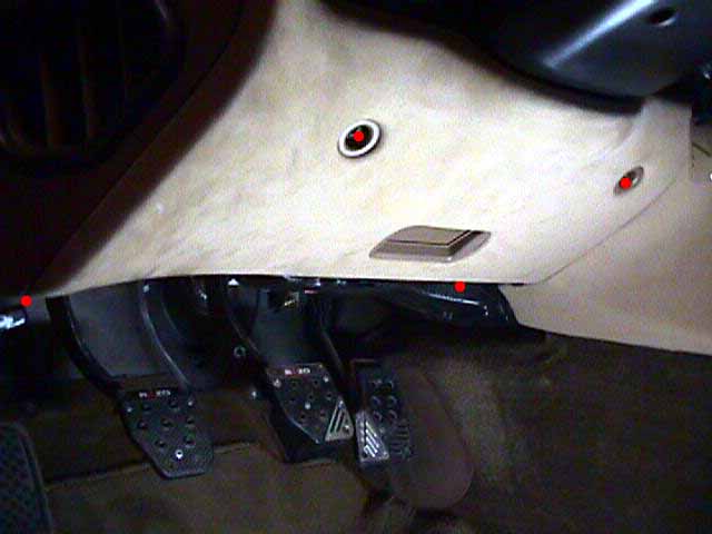
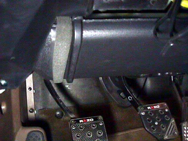
17. Speed shift option installation. Remove the trim panel under the
steering wheel (4 x 10 mm bolts) (red dots in 15.). It's got two
tabs on it to hook it into the dash after the bolts are removed. Remove
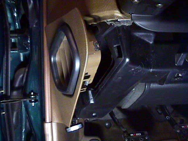
the side vent trim by pulling outwards (16.).
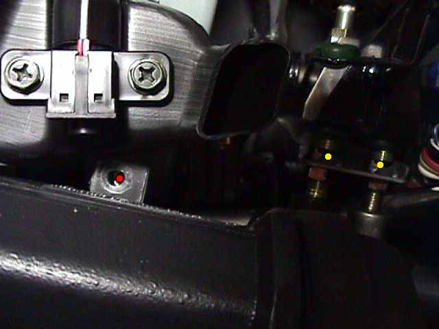
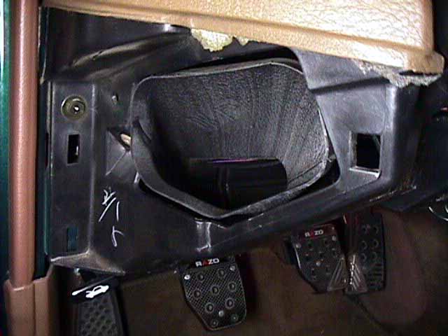
18. Remove the screw holding the lower vent tube to the dash on the
backside of the lower vent tube (1 x phillips) (red dot in 17.).
It's hard to get to unless you lay down on the floor of the car and look
up under the dash. The two upper clutch switches are what we're trying
to get to (yellow dots in 17.)
19. Remove the screw holding the lower vent tube to the steering column
(1 x phillips) (18.). Look at how the outer vent tube connects to
the lower vent tube (19.), pull/twist/whatever to extract the outer
vent tube and the lower vent tube from their current position (20.).
Be careful, there's a sensor on top of the lower vent tube with wires coming
off it.
20. Run the purple wire from the traction control wiring harness over
to the driver side of the car. This will take a few attempts. I've used
a coat hanger stretched out and a bit of electrical tape for the wire to
angle my way across the center console under and behind the radio. As a
last ditch effort, pull the radio section out of the center console to
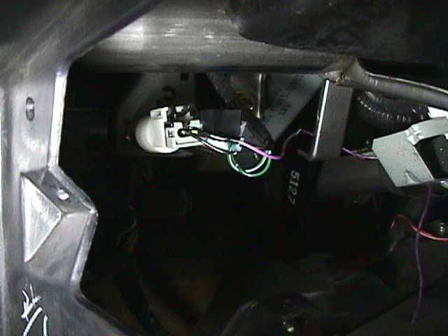
get the wire guided across. Carefully thread the wire to the two upper
clutch switches (21.). Make sure it won't interfere with replacing
the vent tubes, or the motion of any of the pedals.
21. Splice the purple wire into the outer upper clutch switch's non
black wire (I never could make heads or tails of the wiring diagrams in
the service manual). Double-check the continuity of this connection before
splicing into the wire. Is should go to ground when the pedal is pressed
down.
22. Reassemble the underside of the dash.
23. In the main setup menu, select R. for rev limits. There's two ways
of configuring this. I choose having a lower rev limiter for the speed
shift. I have mine set at a hard cut of 04500rpm and a soft cut of 04250rpm
so it will make for near perfect gear speed matches when shifting from
redline. The car can be driven almost like an automatic with it set like
this. The only problem is the clutch switch is *extremely* sensitive. Covering
the pedal with a foot during a series of upshifts will probably prematurely
trigger the rev limiter, causing the car to convulse. Some practice is
involved in making this work out neatly, but the results are very nice
once it's gotten used to. The second way is to configure the hard cut rev
limiter to be about 500rpm under the real redline. This makes for more
drag racing worthy speed shifts, but is hard on the clutch, as the rpms
will have to drop back to the 4500rpm range for the next gear up. The entire
concept of the speed shift function is difficult to get used to. It's very
unnatural to leave the gas pedal all the way down while shift gears. It
definitely takes some time to get used to.
Bernie
Orion
Dallas DamonZ
Back to TECH |