|

You are not currently logged in
Defi-Link Hack to support 2 EGT Gauges
|
This tech page addresses setting up a Defi-Link system to allow control of 2 EGT gauges while only interacting with one visible control unit.
NOTE: This tech page does NOT address installing the gauges in the car. There will be a separate page to address this in the future.
| | |
|
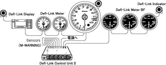
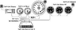
The modular Defi Link system starts with the control unit. All the electronic sensors are connected to the control unit, and the gauges are then hooked up to the control unit in a daisy-chain. Replay (3 minutes), peak hold, warning are all activated through the control unit. The new Control Unit II also features a differential fuel pressure mode, which displays fuel pressure relative to manifold pressure (for 1:1 rate fuel pressure regulators). (0.)
The problem with the out of the box Defi-Link setup for V engine cars is that only one EGT gauge is supported per control unit. The only mechanism for using 2 EGT gauges is to buy a second control unit for the one gauge, which then has synchronization problems, i.e. you would have to press Peak on each control unit to see the peak values for all gauges.
This tech page will address linking two control units together such that a button press on the first unit causes the same button press on the second, which will allow synchronized operation of the second EGT gauge and allows only one unit to be visible.
| |
0.
|
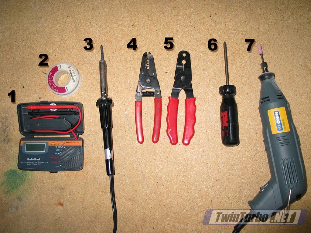
Tools
(1.)
- 1. Multi-meter with continuity and DC voltage capabilities
- 2. Solder (resin core)
- 3. Soldering iron (not a soldering gun)
- 4. Wire strippers
- 5. (optional) 75ohm crimpers. I used them as 'pincers' to hook/unhook the Defi-Link wiring harnesses as the clips are very small.
- 6. Philips head screwdriver
- 7. High speed rotary tool with grinding bit
- 8. (optional) cutting disk for rotary tool
- 9. (optional) SuperGlue
- 10. (optional) drill and very small drill bit
- 11. (optional) needle file
| |
1.

|
Parts:
- 2 Defi-Link EGT gauges (and optional other gauges)
- 2 Defi-Link Control Unit II boxes
- 2 RJ-45 female connectors (purchased mine from Radio Shack, $4.50 each)
- 1 appropriate length of Cat 5 cable with male connector ends (from Radio Shack, 3 feet, $4.99)
- (optional) additional length of Cat 5 cable used to strip apart for wiring inside the Control Units
- (optional) small momentary switch to cut the 'Warning' signal to the other unit
- (optional) toothpick (for extending the momentary switch button)
| |
|
Procedure:
NOTE: The procedure for wiring each unit is identical. In my case, I wired one unit with the external connector on the left and the second unit with it on the right. Therefore in some of the reference images you may see the wires going the opposite direction. The procedure is the same.
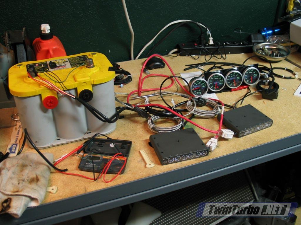
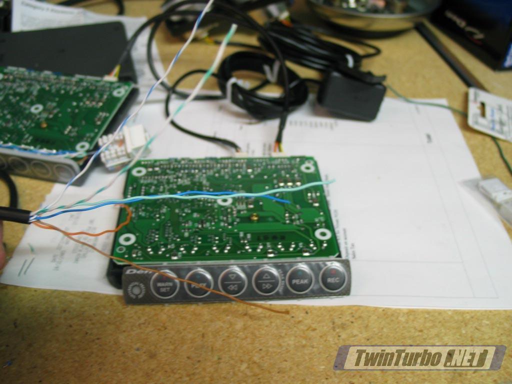
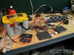
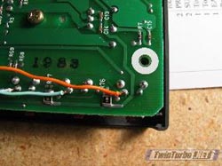
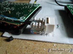
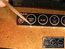
1. Lay out your work area. For full testing, you will need the control units, a battery, the provided harnesses and gauges. In the example shown on this page, you will see a Boost Gauge, a Fuel Pressure gauge, and two EGT gauges. (2.) shows area after everything is complete.
2. First verify that everything works. On the first control unit, plug in the sensors for one EGT gauge and any other additional gauges. This is needed so that the gauges will not go into an error mode when power is applied. The plug locations are noted on the top of the Control Unit case. Plug the gauge harness into the unit and run it to the first gauge. For each additional gauge, run the provided harness from the prior gauge to the additional gauge.
3. Plug the second EGT sensor into the second Control Unit. Plug the gauge wiring harness into that control unit and connect it to the second EGT gauge.
4. Plug both power harnesses provided into each Control Unit. Take the power wires (red, white, and orange) from each harness and tape them to the positive terminal on the battery. Take the ground wires (black) from each harness and touch/tape them to the negative terminal on the battery whenever you want to apply power. If all works correctly, you will see the gauges go through their opening sequence.
| |
2.
|
|
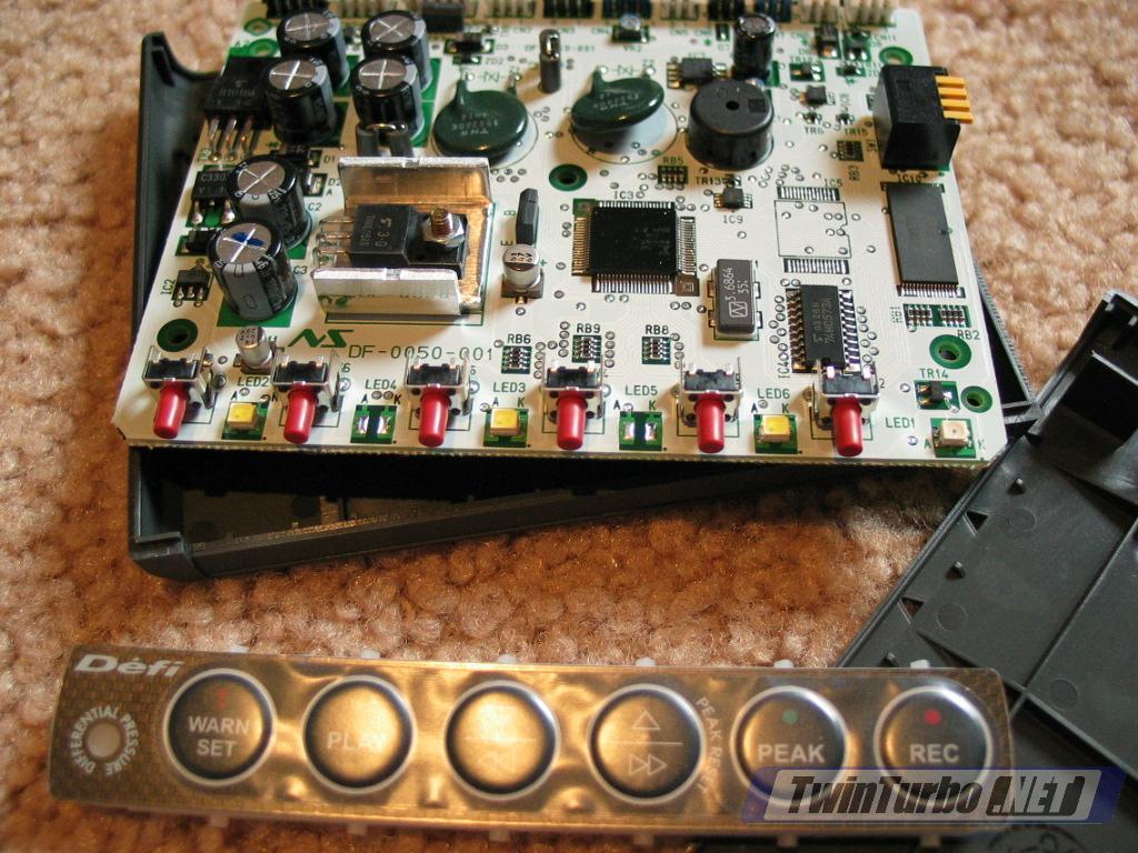
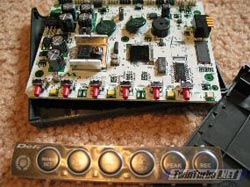
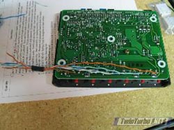
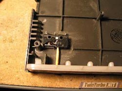
5. Once correct function is verified, remove power and remove the cover on one of the units. There are 5 visible philips head screws to unscrew and then the unit will come apart into 4 pieces, the top cover, bottom cover, button panel, and breadboard. (3.)
| |
3.
|
|
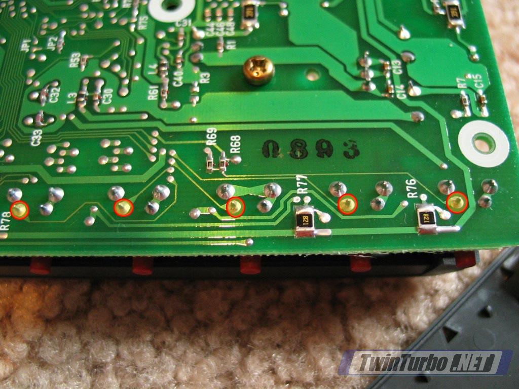
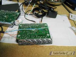
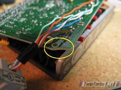
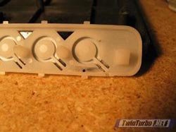
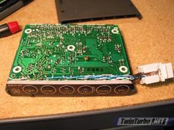
6. You will see 6 buttons with red pushbutton fronts on the breadboard. On the other side of the board you can see 4 solder points for each button. With the buttons facing you, the front left solder point is the signal post that we will tap into. (4.) shows signal posts indicated with red circle.
| |
4.

|
|
7. This step assumes you are using some Cat5 cable as the source for the signal wires. If you use some other wire, apply the same principles. The benefit of using Cat5 wire pairs is that each wire is color coded making it easy to match up to the other side and to the RJ45 connector. Take a length of cat5 cable and split the insulation off of it to expose 4 2 wire pairs. Untwist the pairs and choose 6 wires to use (one for each button). The color choices are irrelevant, but make sure that you match the button/color combinations on both units. In my case I used the brown, orange, green, blue, green/white, and blue/white wires. You can clip off the other two wires as they will not be used. (5.)
| |
5.
|
|
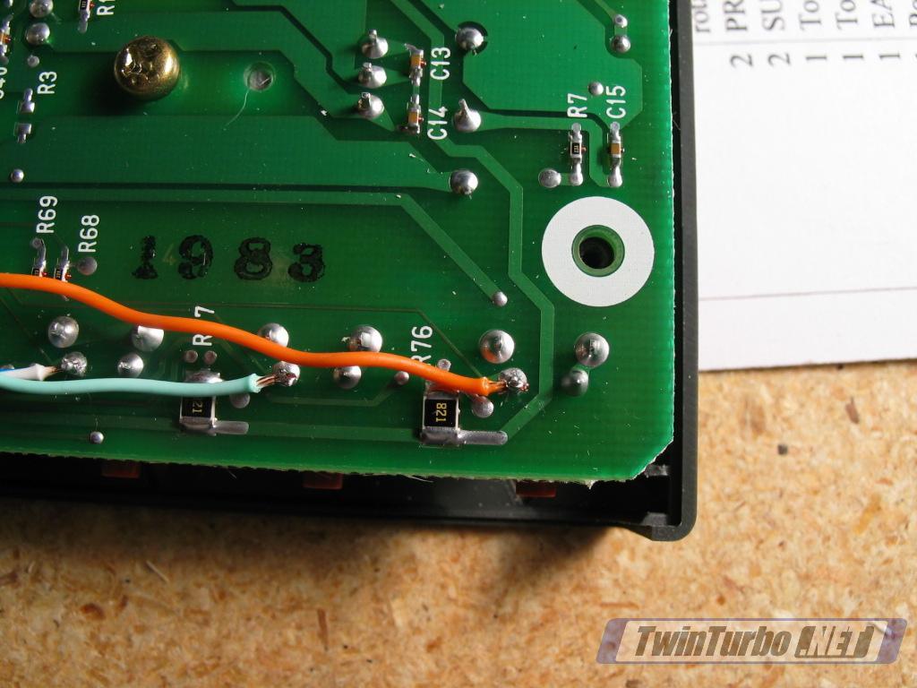
8. Decide which side of the unit you want the connector on and lay the wire out accordingly. Make sure that the wires are long enough for the last wire to reach the furthest button post. Start with the closest button and solder the desired color wire to the post. (6. shows the farthest three posts soldered.)
NOTE: The rest of this tech page shows the RJ-45 connector attached near the front of each unit. After attempting to mount the visible control unit in the center console area, I discovered there was no clearance and had to move the RJ-45 connector to the rear of the unit. Decide where you ultimately want the visible unit mounted and use that information to make a decision about where to place the RJ-45 connector on the unit.
| |
6.
|
|
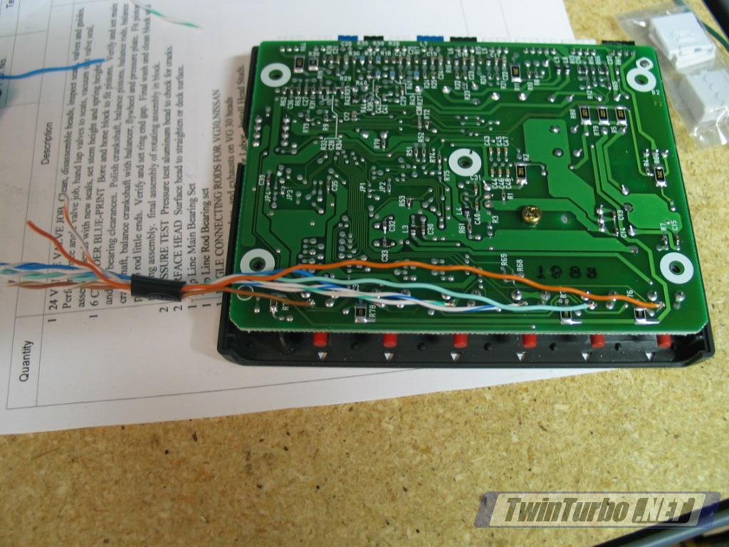
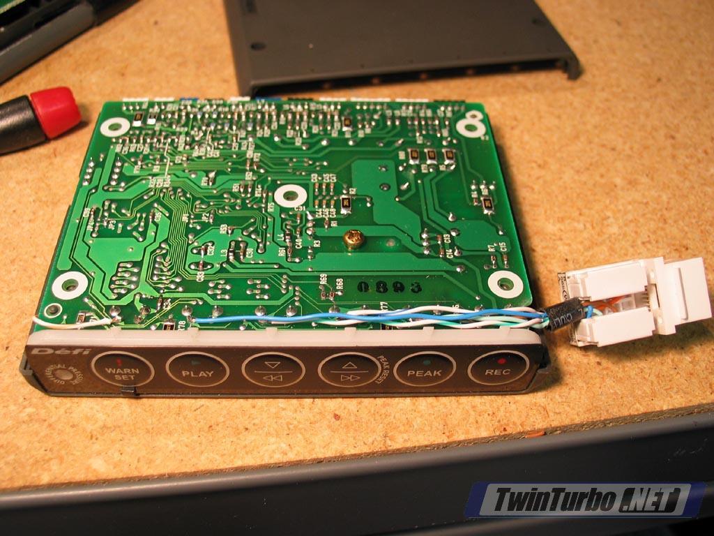
9. Continue with the next closest post, etc. until you have done all 6. Pull the wires tight (remove slack) and decide where you want the RJ-45 connector to extend out of the unit (front/back/middle/etc). (7.) shows completed unit
| |
7.
|
|
10. To allow the wires to run properly without interfering with the case, you need to dremel a small amount out of the breadboard to allow the wires to seat inside it. This shows a chunk out of the left side of the breadboard. If you wired the opposite way, simply dremel out that side. There should be plenty of room but be careful not to dremel out into any of the traces on the breadboard. As well, on the left side, be careful not to dremel into the holes that are already drilled in the breadboard. (8.)
| |
8.
|
|
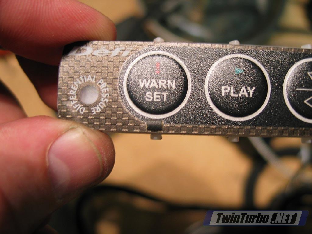
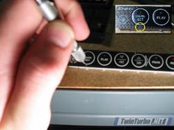
11. To expose the wires outside of the unit, dremel out a small half-moon hole in the upper cover for the wiring to run through. I found that a round sanding bit on the rotary tool (see image 1.) worked very nicely for this. (9.)
| |
9.
|
|
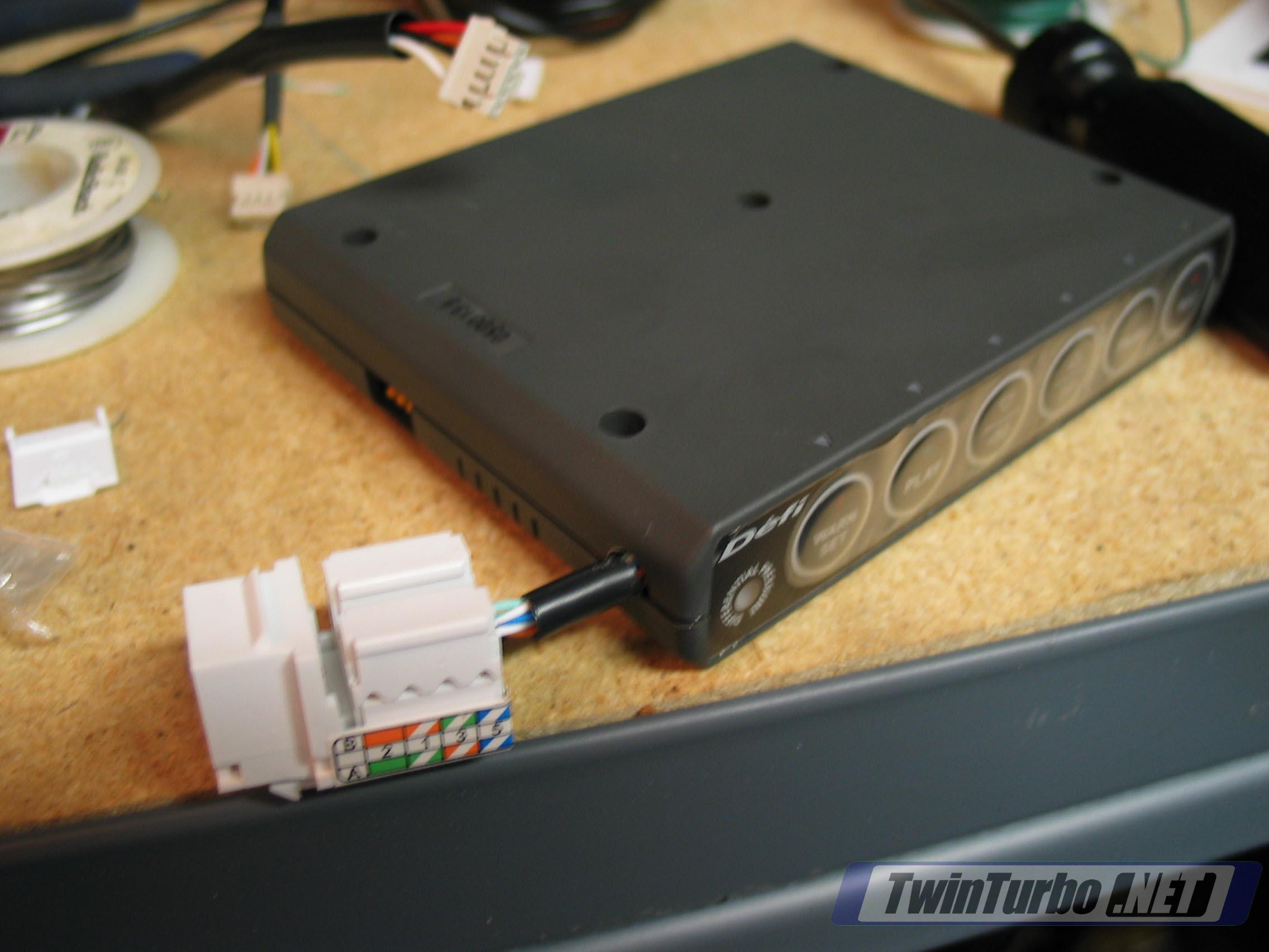
12. Take the six wire ends and position them in an RJ45 female connector. The one that I bought from Radio shack had color codes around the outside that I used to match up the wires. This guaranteed that I would get proper connection between the two connectors. It also came with a small plastic tool to punch the wires into the connector. (10.)
13. At this point, it's probably wise to make sure you have connectivity. Use a multimeter in continuity mode, and touch one probe to each soldered connection while touching the other to the leads inside the female RJ45 connector. You should hear a tone for each one when you hit the right combo. If not, verify all of your solder connections until you do get tone for each one.
| |
10.
|
|
14. Put the button panel back into the base cover. Drop the breadboard in. There is a guiding pin on the front left side that the breadboard has a hole for to line things up. Make sure the wires you have attached are feeding through the dremeled out gap on the breadboard and then put the top cover on. If everything is done correctly, the wires should feed through the hole you drilled in the cover. I left a small run of insulation around the wires, allowing the exposed wiring to be somewhat stiff. The unit is now complete (11.)
| |
11.

|
OPTIONAL STEPS
As it stands now, there is only one problem with the hack, which has to do with setting the warning mode. Warning mode works in a round robin fashion. This means that each time you press the warning button, the unit will cycle to the next gauge that is attached to it. For instance, in my case where boost, fuel pressure, and one EGT are connected the unit will move from EGT -> fuel pressure -> boost -> back to EGT as I press the button. Once the desired gauge is selected you use the up/down keys to change the warning value for that gauge.
The reason that this behavior is undesirable with the hack is because only one gauge is connected to the hacked unit. Since pressing warning on the main unit triggers the same keypress on the second unit, that second EGT will ALWAYS be in warning set mode when you press the warning button, such that if you cycle to boost on the main unit and start changing it's value with the up/down arrows you will simultaneously be changing the setting on EGT 2.
Without following the optional steps, what you will need to do is set all of your gauges on the main unit (while EGT 2 changes willy-nilly) and then finally cycle to EGT 1 on the main unit (EGT 2 will still be in warning mode), zero them both out to get EGT 2 matched up and then set them to the proper level. This is perfectly doable, but I thought it would be painful over time, if you need to frequently change warning levels on the other gauges, so I came up with a solution
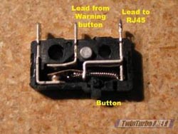
To solve the problem, we simply need to interrupt the signal going to the warning button on the second unit such that it is triggered only when we want it to be. This is done by wiring the Warning button signal lead from the main control unit through a momentary micro-switch and then on to the RJ-45 connector. This will then only allow the signal to trigger warning mode for the second unit when the microswitch is pressed in conjunction with the warning button on the main control unit.
If you do not want to wire a momentary switch, simply follow steps 6-14 for the second unit and then proceed to the TESTING section. If you do choose to install a switch, follow all steps 6-13 for this unit EXCEPT for the Warning button lead.
| |
|
|
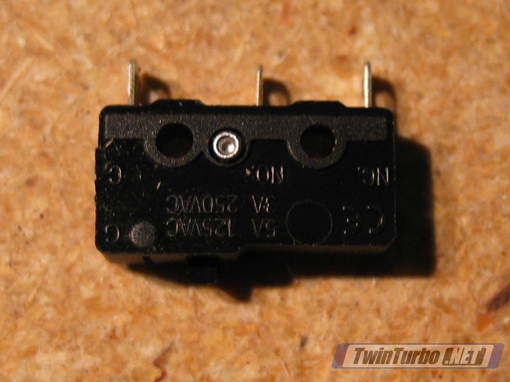
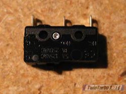
15. I snagged a small three-way momentary switch from Frye's for $1.49. (12.) This switch takes voltage from one side and passes it through one lead when not pressed and through the other when it is pressed. This will require extending the button so I broke the top of the switch off to get at the small button inside it.(13.) If you buy a switch, make sure that it is relatively small form factor, especially in height. In this case, the switch assembly will be placed on the bottom of the case underneath the breadboard and behind the other buttons so there is enough clearance. Verify clearance of your switch before proceeding!
| |
12.
13.
|
|
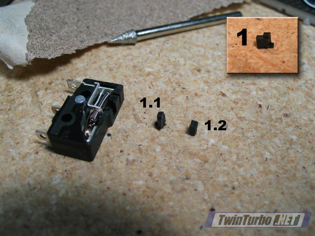
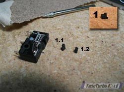
16. Remove the button from the switch and dremel it in half. The back half will go back into the switch and the front half will be on the Control Unit faceplate (14.) 1=original button. 1.1=back half and 1.2=front half after dremeling.
17. Take a toothpick or some other small rod that can be used as a button extension. Cut the toothpick to have a flat end and superglue that end to the back of the visible part of the button.
| |
14.
|
|
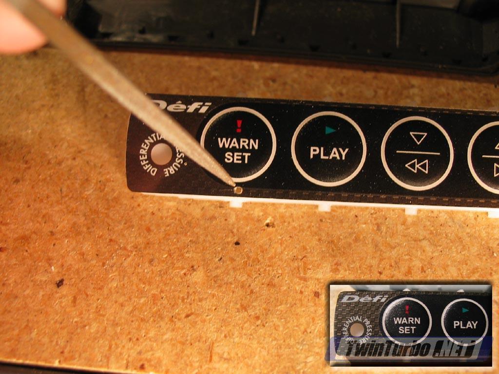
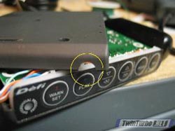
18. Next choose a place for the button to appear on the faceplate. I chose beneath the 'Warning' button so I could roll my finger on both if needed to activate the warning mode on control unit two, giving me single finger operation. I used a small modeling hand drill to drill a hole in the approximate position that the button would be placed. Be VERY careful in deciding placement here as the buttons on the faceplate are attached by a small run of plastic (see rear of plate). If you accidentally drill through that you will ruin the faceplate. There are also LED conduits that have to be considered, which limits your options. (15.) inset shows the hole after completion)
| |
15.
|
|
16. Remove the button from the switch and dremel it in half. The back half will go back into the switch and the front half will be on the Control Unit faceplate. (14. 1=original button. 1.1=back half and 1.2=front half after dremeling.)
17. Take a toothpick or some other small rod that can be used as a button extension. Cut the toothpick to have a flat end and superglue that end to the back of the visible part of the button.
| |
|
|
19. Dremel out the plastic on the rear of the faceplate to give clearance for the small button to fit. Be very careful not to dremel all the way through and stay well clear of the thin runners for the faceplate buttons. (16. shows completed dremel work)
| |
16.
|
|
20. Take a needle file and use it to carefully enlarge the hole. (17.)
21. Continue with the file and create a hole sized for the button front to be able to come through and move easily. (17.) (inset) Work carefully and don't rush this part. If the hole gets too big you've just ruined the faceplate.
| |
17.
|
|
22. Take the button/toothpick combo and verify that it seats in the newly created hole properly. (18.)
| |
18.

|
|
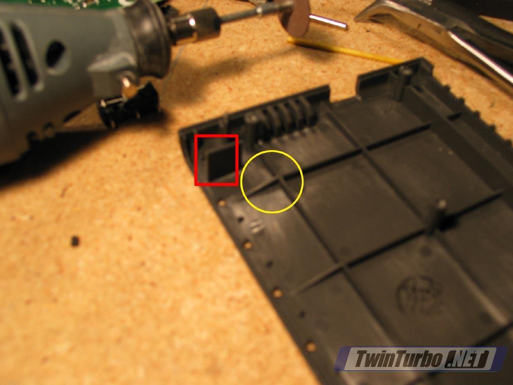
23. Take the bottom case and determine required placement of the switch based on where you drilled the front panel button hole. You will probably have to dremel off some of the plastic supports to make room for the switch (yellow area in 19.). Make sure you do not remove the square support that separates the differential pressure LED from the rest of the panel (red square in 19.)
| |
19.

|
|
24. Put the front button panel with the extended button/toothpick combo installed into the bottom part of the case. Use this to determine where to mount the actual switch and superglue the switch into place. If done properly you can then trim the end of the toothpick to fit inside the switch assembly to press against the back half of the button that we dremeled off before, causing the switch to trip. (20.) shows glued and working button assembly
| |
20.
|
|
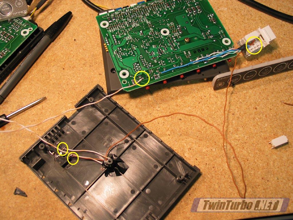
25. Solder connection from Warning button to one pole of the momentary switch. I used a long length of one pair of the cat5 cable. I wrapped the wire around the center pole to hold it steady to the switch and kept some excess coiled up in the case to allow the breadboard to be removed in the future and set to the side since the momentary switch is glued directly to the case. (21.)
26. Solder connection from other pole of momentary switch and run it to the RJ45 female connector and punch in. I used the same tactic here as I did in step 25. (21.)
| |
21.

|
|
27. Dremel the breadboard and case as explained in steps 10-11. Put this unit back together with the momentary switch installed. (22. shows completed primary unit with exposed momentary switch button)
| |
22.
|
TESTING
28. Plug Category 5 network cable into both RJ45 connectors to connect the two units together.
29. Power up the units as explained in Step 4.
30. Verify that pushing Peak on one unit causes all gauges to go into Peak mode.
31. Verify that pushing Record on one unit causes all gauges to go into Record mode.
32. Verify that pushing Play on one unit causes all gauges to go into Playback mode.
33. Verify that pushing Warning causes the first gauge on unit one and the EGT gauge on unit two to go into Warning set mode. If momentary switch was installed, the EGT gauge on unit two should NOT go into warning set mode.
34. If momentary switch is installed, hold momentary switch while pressing Warning should cause EGT on second unit to go into Warning mode.
35. On any gauge in warning set mode, verify that the up/down buttons move the warning level on the gauge.
36. Get the EGT on unit two into Warning mode (Step 33 or 34) and then verify that pressing the up/down buttons on the primary control unit cause the EGT warning levels to change.
Congratulations! Your Defi-Link system is ready for installation!
| |
|
|
(23.) Shows the final configuration of the three gagues in the 300Degree pod (boost gauge is on the A pillar) with a single control unit visible where the stock clock was. The second control unit is hidden behind the gauges in the console cavity.
Originally published 02-27-2004
Greg (Dallas)
Back to TECH |
|
23.

|
|