| Typically, the first step in increasing boost to gain more
HP on TTs is getting a Jim Wolf ECU and 'boost jets'. Boost jets are good
for about 12.5-15 psi. However, to run higher boost levels (or to run more
steady low boost levels) requires and electronic boost control. If you
expect to run more than 12 PSI an upgraded ECU is a must! The remapped
ECU is critical to keep proper air/fuel ratios at higher boost levels the
stock ECU can't handle. Also larger injectors are needed (555 cc or bigger)
to run over 15 PSI of boost safely. The stock 370 cc's won't be able to
handle the larger fuel load required.
Wastegates control the amount of boost turbos create. When they are
closed, the turbo is the only pathway for air to follow. When the wastegates
open, they allow an alternate path for air to move through, allowing boost
to drop. The wastegates are controlled by a pair of actuators that move
depending on the amount of vacuum pressure applied to them. In stock form,
the amount of vacuum is a function of the entire system. With boost jets,
the amount of vacuum is restricted slightly, keeping the wastegates closed
longer, but vacuum is still a function of the system. As a side note, the
stock design has a set of boost cut solenoids in the vacuum pathway to
vent any vacuum from getting to the wastegate actuators. The stock wastegate springs, set at 6 psi, are the only things controlling the boost as a fail safe. This is known as 'safety boost'. Generally
when an EVC is installed, these solenoids are removed from the pathway.
This is good and bad: Good because there's no more safety boost. Bad because
safety boost exists for a reason, to protect the engine's functions. Operation
of an EVC (Electronic Valve Controller) or boost controller is pretty straight
forward. It regulates the amount vacuum applied to the wastegates to control
the total amount of boost produced. The wastegates are now controlled indirectly
by the electronics, still utilizing vacuum provided by the system to the
actuators, but in a more controlled fashion. It uses a solenoid to maintain
a specific vacuum. In the case of the AVC-R this is accomplished by controlling
the solenoid duty cycle which determines how long the solenoid stays
closed vs. open in a 40 msec cycle, and can be based on RPM, Gear, and
Injector Utilization. Another nice feature of the Apex'i AVC-R is that
will allow monitoring of a series of functions such as boost pressure,
duty cycle, injector utilization, RPM, etc., and can provide a peak hold
or a linear map of the results.
For more information on the AVC-R, take a look at http://www.apexi-usa.com/superavcr2.htm
The following procedure is compiled from three installations on '90-'93TTs
Special Tools:
Drill and drill bits Carbide bits if mounting the solenoid on the
front bumper.
Soldering iron
Solder
Other Items:
Electrical Tape
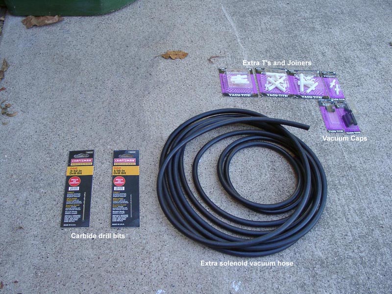
10' to 20' of ¼" vacuum hose
Although hose comes with the kit, it wouldn't hurt to get some extra,
and it's cheap. Re-using the stock boost hoses (the orange lines in
4.)
requires 10' of hose. To replace everything requires 20'. The differences
are explained later.
2 - ¼" Barrel connectors
Zip Ties Both short and long. The ones provided won't be enough.
¾" #12 nuts, buts, and locking washer or self tapping screws
For
the solenoid mount
½" #10 self tapping metal screws
A pair of self tapping metal screws
2 - ¼" Hose clamps
Wire coat hanger
Preparation:
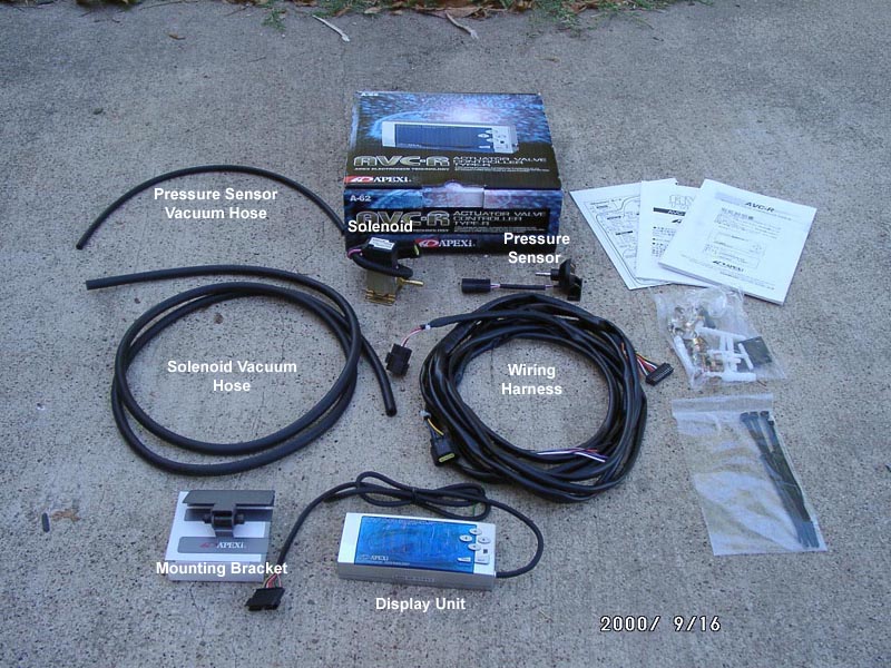
1. Read these instructions entirely and make sure to have all the items
and tools necessary. This includes an inventory check to make the AVC-R
kit is complete. Make sure to get everything now as not to be missing something
then suddenly having to go out and get it, only to find the store is now
closed.
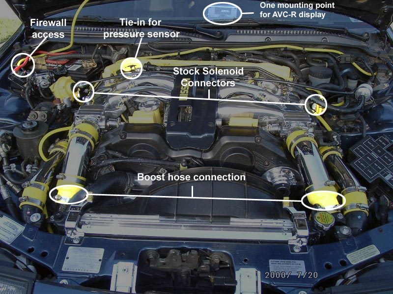
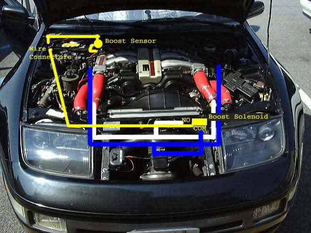
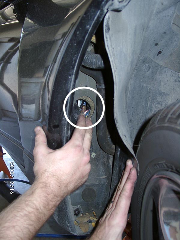
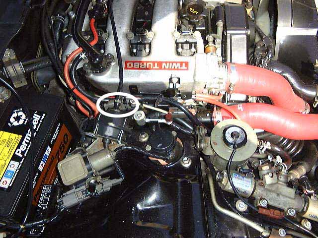
2. Use picture 3. to locate the following items on the car:
ECU location (passenger floorboard, not shown in 3.)
Boost solenoid electrical connector (one on each side of engine)
Vacuum hose on passenger side of balance tube (pressure sensor tie
in)
Fender opening beside the battery and firewall access inside the passenger
fender well
stock vacuum hose that goes to stock solenoids (boost hose connection
in 3.)
Procedure:
There are 5 distinct components to the installation:
I. Run wiring harness and splice into ECU
II. Install the pressure sensor
III. Install the solenoid and all vacuum hoses
IV. Install and connect the display unit
V. Set up the AVC-R parameters
I. Run the Wiring Harness and Splice Into the ECU
1. Disconnect the battery ground. Turn the steering wheel all the way
to the right, exposing the rear of the passenger fender well.
2. Remove the windshield trim overhanging the battery. There are typically
two plastic phillips type connectors. If careful (and they're not too brittle),
unscrew the center 'screw' then pop them out and reuse them later. Loosen
the terminals of the battery and remove them. Remove the battery bracket
and then pull the battery and take care not to sit it directly on the ground
which will cause it to drain and be ruined. It's best to sit it on a table
or a piece of wood. Locate the hole in the fender wall at the base of the
battery compartment. It may have a black plastic shield covering it which
can be removed. (6.)
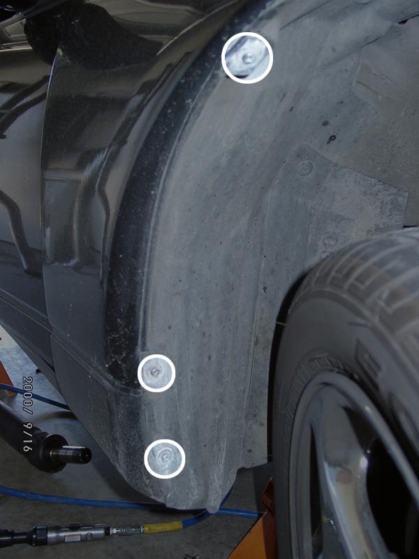
3. Next remove the screws on the passenger fender liner (7.)
to gain access through the firewall into the passenger floorboard area
where the ECU is located. If there is a mud guard installed, remove it
to get full access.
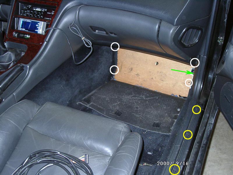
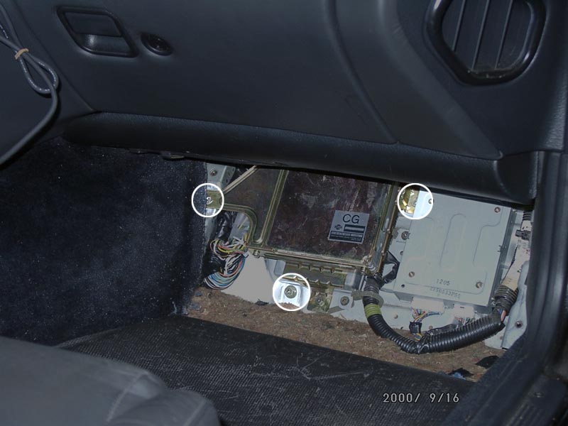
4. Expose the ECU by pulling up the passenger floorboard carpeting.
Use a 10 mm socket to remove the 4 bolts holding the wooden panel in place(8.
- White circles). Remove the running board trim (8. - Yellow
circles). Remove the passenger side kick panel. There is a sunken
phillips head screw that holds it in place (8. - Green arrow).
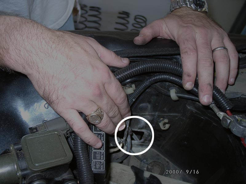
5. Feed the AVC-R wiring harness through the hole by the battery (6.).
Use a straightened coat hanger and electrical tape one end of it to the
AVC-R wiring harness where the bundle of colored wires is hanging out.
This will help feed the wiring harness through the firewall. Look inside
the fender well and pull loose the big rubber boot that protects the main
wiring harness. (9.) This exposes a hole through the firewall. Feed
the coat hanger through the firewall and it will poke out in the ECU compartment.
Get inside the car, grab the hanger, and gently pull the AVC-R wiring harness
through. Also have pull the display unit connector of the wiring harness
through. Make sure to pull enough cable through to connect to the display
unit in desired mounting location. More on this later. Remove the coat
hanger from the harness. I use an Xacto knife and cut a notch in the rubber
firewall boot so it can be put back in place and allow the AVC-R harness
to rest in that notch.
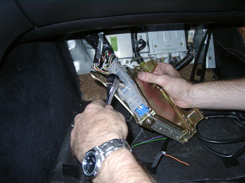
6. Remove the ECU from the floorboard (3 x 10 mm screws) (10.)
Then remove the ECU harness cable by unscrewing the plastic holder (1 x
10 mm) (11.). Now the tricky part. The AVC-R wiring harness needs
to be spliced into the ECU harness. If using snap-on 'piggyback' connectors,
this will go fast. All three of the installs contributing to this page
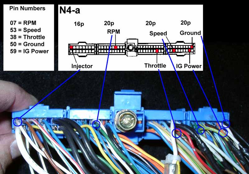
use a solder splice for a more secure connection. Refer to picture 12.
for splice points. Note that the circles show the relative location
of the connection. They are not necessarily circled around the proper wire
color. The following table shows the relationships of the AVC-R harness
wires to the ECU wires.
| Function |
AVC-R Color |
ECU color |
Pin # |
| IG Power |
Red |
White |
59 |
| RPM * |
Purple |
Yellow/Red |
07 |
| Ground |
Green |
Black |
50 |
| Ground |
Black |
Black |
50 |
| Throttle |
Gray |
White |
38 |
| Speed |
White |
Yellow/Green |
53 |
| Scramble |
Orange |
N/A |
N/A |
*The purple wire from the AVC-R is either connected to the RPM signal
(as shown in the chart) or to the injector wire. All three installations
for this page have connected it using the RPM signal on the ECU.
NOTE: For the ground wires, splice both the green and black wires
to a single ground wire on the ECU. Splice the GREEN wire closest to the
ECU connector and splice the black wire 1/2" further away. Sounds odd,
but is rather critical.
My preferred method of splicing is the military splice. It takes a bit
more time but guarantees a solid connection. Take the target ECU wire and
strip away a piece of the insulation. Using a small screwdriver or other
pointed tool, poke a hole through the bundle of exposed wire strands. Next,
strip the end from the appropriate AVC-R wire, feed it through that hole
and wrap it securely around the ECU wiring. Then, use a soldering iron
and heat up the wire until the solder will melt on the wire (not the iron),
this prevents a 'cold' solder from happening (breaks apart easily). Use
electrical tape to wrap up the splice and make sure that it can't touch
any other bare wire. A small zip tie over the electrical tape ensures it
doesn't go anywhere. The best method for insulating is using heat shrink
tubing and a heat gun.
7. Re-connect the ECU harness to the ECU and reinstall the ECU by reversing
the removal procedure. Make CERTAIN that you tighten the screw on
the ECU harness all the way down. Then push in both ends of the connector
to ensure a good seat in the ECU.
II. Install the Pressure Sensor
8. This entire procedure references picture 13. The best mounting
place for the pressure sender is on the firewall behind the balance tube.
Use two self tapping screws to mount the sensor.
9. Use the supplied 1/8" hose and secure it to the bottom of the sensor.
I prefer to use zip ties to secure all vacuum connections, but the provided
brass clamps work too.
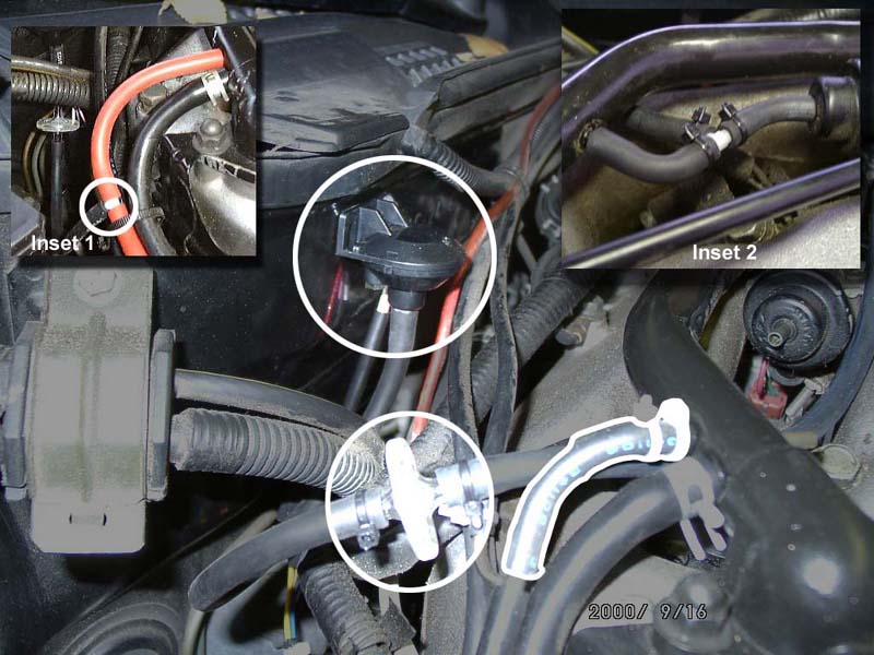
10. Determine where to tap into the vacuum system. On Carlos' install,
the stock boost gauge hose was used (Inset 1, 13.). On Greg (Dallas)'
and nixit (Da][as)' installs, the sensor was tapped into the vacuum hose
running between the balance tube and the fuel dampener (Inset 2, 13.).
Carlos' method is probably easier as the hose for the fuel dampener is
very short which makes it harder to deal with. Cut the selected system
vacuum hose and insert one of the small T's. Then attach the other end
of the pressure sensor hose to the T. Secure all connections with zip ties
or hose clamps.
11. Find a point on the new hose and cut it to insert the AVC-R supplied
air filter, which is the clear top/UFO looking thing. (Circled in 13.).
Again secure the connections with zip ties or hose clamps. These tend to
fail over time, if problems arise later, this is the first item to check
for leaks.
12. Connect the sensor into the wiring harness. From the hole in the
fender wall by the battery (6.), run the sensor connector around
the back of the battery compartment along the firewall and secure it in
various places with zip ties. Be SURE to not let the harness hang close
to the plenum or other part of the rear of the engine that will get very
hot. Disconnect the stock boost solenoid electrical connectors. There is
one on each side of the engine. The easiest way to spot them is they are
rectangular black connectors... everything else is grey. (14.) (15.)
III. Install the Solenoid and All Vacuum Hoses
13. Remove the throttle body hoses. These are the big black hoses in
the front of the engine. I recommend marking them if the factory colored
paint dots are worn off or keep track of them to know which side is up
and what hose belongs where. A good idea is mark the hoses from left to
right as 1,2,3 and 4. This will only save headache later if done now. Once
the hoses are removed stuff the opening with some shop towels to avoid
anything falling inside. This is a good time to do a throttle
body cleaning.
14. Remove the center panel (4 x 10 mm). On '90 models there may only
be 2 bolts.
Depending on where the solenoid will be mounted (see next item) the
intake might need to be removed. This entire procedure assumes a cone intake
is installed. To remove it, first release the mass airflow sensor connection
which is the black box just above the cone part of the intake. Unscrew
the filter from the shield, if it's connected. This is located on the end
of the filter. Loosen the two hose clamps on each end of the larger rubber
T using a flathead screwdriver or 8 mm socket and pull the entire intake
assembly out. Stuff rags in the remaining openings to make sure nothing
falls into the intake tracting.
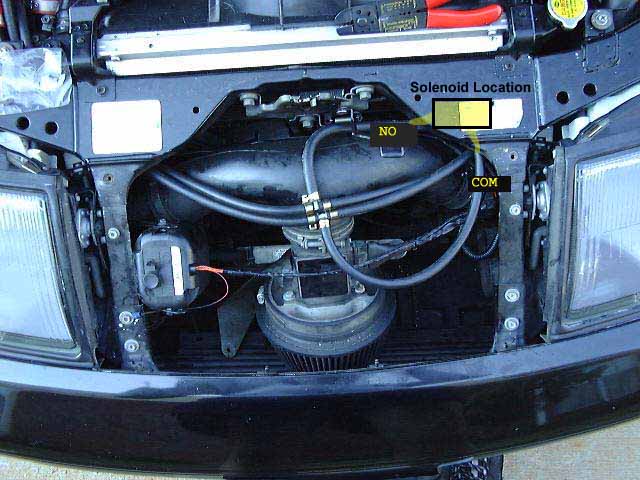
15. There are several different mounting places for the solenoid. Pick
a favorite. On Greg's Z it is mounted directly against the front bumper.
On Carlos' Z it's mounted on the driver's side behind the POP charger.
On nixit's Z (displayed in the images) it is mounted on the passenger side
headlight wall near the bumper. Things to consider for placement: Make
sure the vacuum hoses can't be interfered with by the auxiliary fan. If
planning to install a dual POP charger later, put the solenoid where it
won't have to move again.
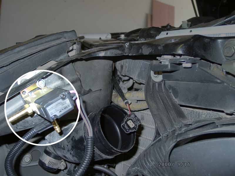
16. If mounting the solenoid directly on the back of the bumper, the
carbide drill bits are needed to drill through the steel. Otherwise, normal
drill bits can be used. Get the rectangular black rubber 'cushion' out
of the AVC-R bag of parts and use it as a template to drill your holes.
There are four screws but two should be plenty. Drill the holes, then secure
the solenoid in place with the screws. Make sure to put the rubber 'cushion'
between the solenoid and the mounting point. Nixit's installation is
shown in (16.).
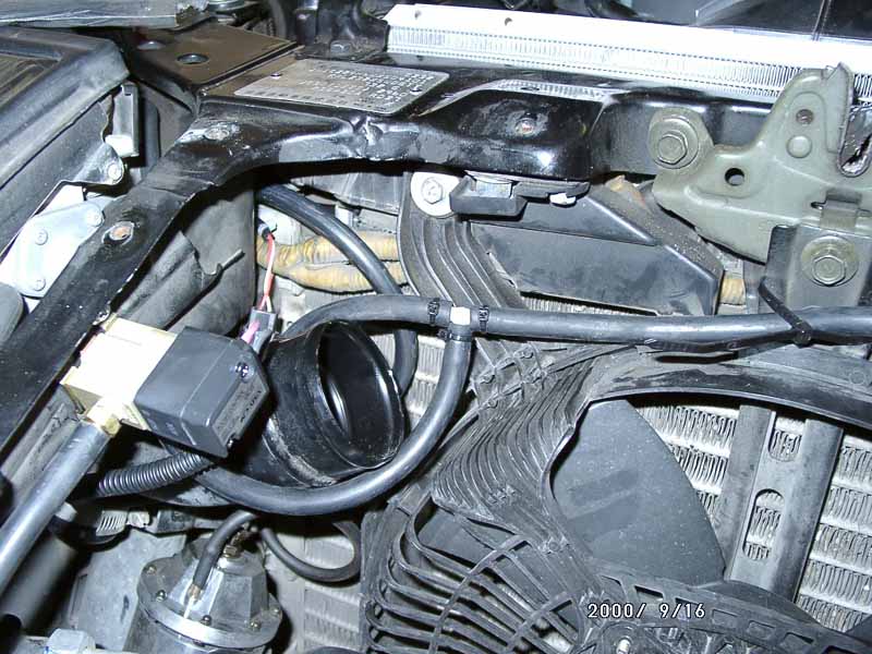
17. Thread the electrical harness for the solenoid from the battery
compartment forward to the center panel area. There are several points
along the way to zip tie it down to make the installation neat. Poke it
through an opening by the radiator on the passenger side. (17.)
Connect the harness to the solenoid.
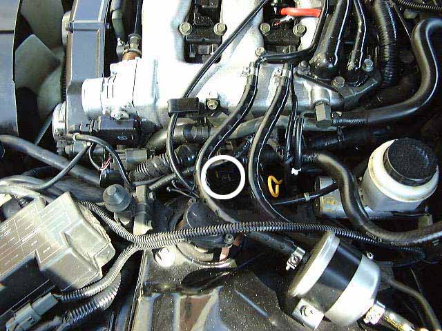
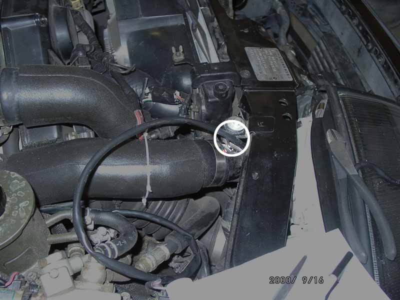
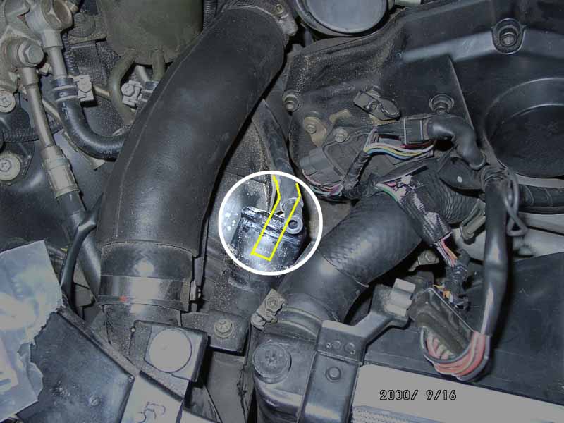
18. Disconnect the stock boost hose underneath the INTAKE pipe
on each side of the engine. This is the pipe connecting up directly to
the throttle bodies. (passenger side 18.) The yellow lines indicate
where the hose actually connects underneath the hard pipe. (driver side
19.) points out the correct hose.
NOTE: On the passenger side, make SURE to remove the correct hose.
The stock recirculation valve hose connects to the other hard pipe on the
passenger side. The line in question is closest to the radiator.
If boost jets were installed, they will be in the ends of these two
hoses. If they're close to the end, use a pair of needle nose pliers to
squeeze the hose behind the jet and work it forward and out of the hose.
or cut the hose behind the boost jet.
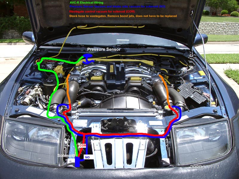
19. The easiest way to install the AVC-R is to simply
connect new hose to the ends of these boost hoses which go down to the
wastegate actuators. By disconnecting the stock solenoids earlier, it effectively
kills the stock boost control system. However, contrary to what many people
believe, there ARE stock boost jets installed at the other end of
these hoses (near the stock actuators). By leaving this hose in place the
car will run slightly higher 'natural' boost, i.e. when the AVC-R is totally
off, it will still be able to run about 9 PSI. With these hoses completely
removed and replaced by new hose, it will run the correct 'natural' boost
of 7 PSI with the controller turned off.
20. Greg's installation completely replaced the hose all the way to
the wastegate. The main reason this was done is because he was already
down in the engine replacing the valve covers and plenum. Both Carlos and
nixit used the existing hose because it's a lot less work. If choosing
to replace the entire hose, remove the hard pipes running alongside the
engine to get to the other end of the hose. There is a T down there connecting
the hose to the wastegate actuator and the stock boost cut solenoid. Connect
new hose in at this point and cap off the stock solenoid with a vacuum
cap. Sorry, no pics of this procedure as Greg didn't have the digital camera
when he did the work on his car.
21. Connect the ¼" hose to the output where the stock boost was
connected on t he hard pipe up front and use the clamps provided with the
AVC-R kit or zip tie them down. Run through the headlights around past
the center panel and back onto the other side. Yes, this is a loop!
NOTE: Since the hose has to loop back on itself to go to the
front of the car, take care that you don't get a tight crimp in it. Also,
be careful on the passenger side not to end up with an excess of hose in
that area near the alternator pulley.
22. Now connect a ¼" barrel connector to the stock boost hose
for both the driver and passenger side and clamp or zip tie them down as
well. Run another piece of new ¼" hose from one barrel, through
the headlight, center panel area, headlight and connect it to the other
barrel connector on the other stock hose. Loop #2. Clamp or zip tie everything
down.
23. Tie the solenoid into these two loops. Split each loop in the middle
to make an equal length on each side. Insert a ¼" T connector. Cut
an appropriate length of hose and run from the solenoid to the T. Connect
the COM side of the solenoid to the loop that goes to the wastegates. Connect
the NO side to the loop that is connected to the front hard pipes (intake
side). Clamp or zip tie all connections. Finally, secure the hose to various
parts of the car (frame walls, auxiliary fan, etc.) with zip ties to keep
the hoses secure. Take care, if necessary, that the hoses cannot come in
contact with the opening in the auxiliary fan. Pictures 20. &
21. show different approaches for the hose connections and solenoid
placement.
NOTE: Picture (21.) was taken before the install was finished.
Do not leave loops in your vacuum hose as is shown in the picture. After
the picture was taken we pulled the rest of the hose through and got rid
of the loops. Also, the T's in Nixit's install are closer to the passenger
side so they wouldn't lay over the cone intake. However, the length of
hose is still the same to the passenger and driver's side. We just allowed
more hose on the passenger side that is not seen.
24. Remove the rags from the intake tracting. Reinstall the intake if
it had to be removed. Reinstall the throttle body hoses.
IV. Install and Connect the Display Unit
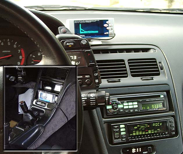
25. This part is very subjective and just depends on personal preference.
Greg (Dallas) installed it using the supplied bracket on the dashboard
above the center console. Carlos installed it in the second DIN slot of
the center console and nixit's is installed in the glove box. Picture (22.)
shows a couple of options.
V. Set up the AVC-R parameters
26. Reinstall the battery and connect the terminals. Reinstall the trim
piece above it.
27. Start the engine. Go to the engine bay and listen for leaks, locate
any and clamp them down tighter.
28. Enter the monitor section of the AVC-R and see if it reports a good
throttle position (surge the engine to check), a good boost pressure (should
be about �1 Bar), speed should be zero as the car is not moving, and RPM
should be very close to what the dash reads.
29. There's been quite a bit of debate about how this thing actually
works. Basically, the FIRST thing to do is go to Car Settings and do the
following:
Cyl: 6
Speed: 2
Throttle: rising arrow from left to right
Decide how much boost to run. If there is not an upgraded ECU installed,
set the boost no higher than .8 bar (roughly 12 psi) to be safe. If there
is an upgraded ECU, and stock injectors, set it to 1 to 1.05 bar (14 -
15 PSI). If there are 555 cc injectors, set it to around 1.15 - 1.2 bar
(17 - 17.5 PSI).
NOTE: These are just GENERAL guidelines. Remember, too much boost
will kill the engine fast, so if deciding to run extreme amounts of boost,
don't come cry to us when the motor explodes on the freeway. Basically,
this means take some responsibility for your actions, because we won't.
30. The AVC-R has three setting modes, A, B, and OFF so there are two
different boost settings. Choose one of them and set the base boost level
as desired. What actually controls the amount of boost is the duty cycle,
not the boost setting. For 1 bar, try starting around 58%. Higher percentages
= higher boost.
31. It is a good idea to find out what the 'natural' boost is with the
system off. Set the AVC-R to OFF (hit the left arrow in the selection mode).
Then go to the boost monitor screen. Find a stretch of deserted road and
make a wide open run in 3rd or 4th gear (4th goes to ~126 MPH). The boost
monitor screen should tell what peak boost was. It should be around 0.5
- 0.65 bar (7 - 9 psi). This will show what the car will boost with no
boost controller at all (Good to know). Put the AVC-R in the desired boost
mode (A or B), get into 3rd or 4th gear again, and go full throttle again.
If it boosts over your target amount, reduce the duty cycle and try again.
If it boosts under, raise the duty cycle.
32. Once it boosts correctly, make 2 more runs in succession (this means
wide open throttle). My understanding from LRD VDR and others is this triggers
the AVC-R into self learning mode which is supposedly a 'good thing'. Go
back to the boost setting screen and if the duty cycle displays '***' then
it is in self learning mode and you're good to go.
Greg (Dallas)
Carlos Ramirez
Other Credits:
Greg:
Thanks to Kyle @ SGP who sold me my AVC-R and gave me the first introduction
to it when I installed it on my car.
Thanks to LRD VDR who has helped me understand it a bit more than I
did before.
Thanks to nixit (Da][as) who was a willing guinea pig for my second
install :-)
Carlos:
I like to give credit to Sam from http://www.jspec.com/
who sold me the AVC-R,
to Gyro from DSP Racing who helped me with some of AVC-R settings,
to Orion (John) from TT.NET who helped me with various questions, and
to Tom Bullinger who's web site I used as reference in the installation
process (http://www.frontiernet.net/~tomb/BoostController.html)
Back to TECH |