| This page is intended to assist in understanding when the fan should
work and provide some diagnostic tips for checking and testing components.
It is intended for the more experienced DIYer. Please read the ENTIRE page,
including conclusions and the �Fine Print� before starting any actual work.
For Z32 owners who are having overheating problems, this item is only
one of the many to be considered in seeking a solution. However, if all
the �common� causes have been checked and vehicle overheating primarily
occurs during periods when the fan should be running, certainly the fan
and its control system becomes a prime suspect.
Operating principles:
In the Z32, the electric fan located in front of the radiator (a �pusher�)
is an auxiliary unit designed to come on under very specific conditions,
providing extra cooling capacity when needed. In many situations
these operating conditions may never be met and the fan may never come
on.
This auxiliary fan serves to assist both the cooling system and the
A/C system. In addition to adding radiator cooling capacity related to
overheating, it also improves A/C condenser heat exchange, therefore A/C
operation.
The NA Z32 has a single speed auxiliary fan. The following specs are
for the NA fan, and come from the Nissan service manual. Temps are in Fahrenheit:
A/C off, coolant temp below 219 = fan off
A/C off, coolant temp above 221 = fan on
A/C on, vehicle speed < 24mph, coolant below 201 = fan off
A/C on, vehicle speed < 24mph, coolant above 203 = fan on
A/C on, vehicle speed > 25mph, coolant below 219 = fan off
A/C on, vehicle speed > 25mph, coolant above 221 = fan on
The TT Z32 has a two speed fan. The following specs are for the TT fan,
and also come from the Nissan service manual with temps in Fahrenheit:
A/C off, coolant temp below 219 = fan off
A/C off, coolant temp above 221 = fan on
A/C on, vehicle speed < 24 mph, coolant between 194-210 fan = low
speed
A/C on, vehicle speed < 24 mph, coolant above 212, fan = high speed
A/C on, vehicle speed > 25mph, coolant below 219 = fan off
A/C on, vehicle speed > 25mph, coolant above 221 = fan on
As you can see, the fan is ECU controlled (A/C, temp & speed sensor
input feeds to ECU, output from ECU for fan operation). It is also
obvious the fan should not run very often if the cooling system is operating
efficiently.
Diagnostics:
1. Observations: Make sure the fan blades are clear of all obstacles
and can turn freely. Their position on the lower part of the Z tends to
make them subject to debris collection. I have found plastic bags wrapped
around mine and a hunk of styrofoam wedged such that the fan could not
turn. Also check 10 amp fuse marked �air cond� on relay box cover
(front of the driver's fender hump under the hood) (1.) and check
the fusible link marked �rad fan� in the box directly in front of the battery
(2.).
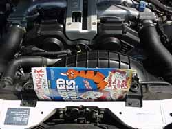
2. System check (read the notes at the end before starting this step):
To force the system to behave under the non-speed sensitive conditions,
slide a thin piece of cardboard (like an unfolded cereal box) (3.)
down between the radiator and A/C condenser (just in front of the radiator
cap) to obstruct airflow from the engine fan (which is a �puller�). On
a hot day, just partially restricting airflow may work. On a cool day or
with a very efficient system, it may be necessary to remove the two top
radiator brackets to completely block the airflow across the entire radiator.
On a real cool day the coolant temperature may not rise enough to successfully
perform this test. Start the engine, turn the A/C on and monitor the temp
gauge and fan operation. When the gauge gets somewhat (1/8th to 3/16s of
an inch) above its normal position, the fan should come on. If it does,
OR if the temp gauge begins to approaches the H mark and the fan has NOT
come on, remove the cardboard, turn the A/C off and turn the heater on
full hot. Let engine continue to run until engine temp returns to normal.
If fan does not operate then troubleshoot starting with step 3, Circuit
test.
If the fan does operate, it is unlikely the fan operation is the cause
of the overheating problem.
Note 1: This �trick� will not hurt the car as long as it's not allowed
to get too hot or be too prolonged a period of time. The heater assists
in the cool down by exiting heat into the cab, and is a good trick to remember
if it overheats on the road to control the temp until it can be serviced.
Note 2: Making a hole about an inch from the edge of the cardboard and
tying a string to it will allow for easy retrieval if it slips too far
down.
Note 3: The system check is good operational check of the system but
not entirely necessary for troubleshooting the system. If desired,
simply proceed to step 3, Circuit test.
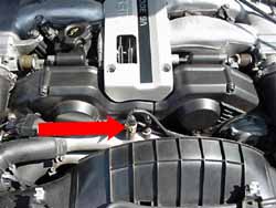
3. Circuit test: Test the circuitry without the temp sensor in the circuit.
Remove the connector for the temp sensor. The open circuit will cause the
ECU to detect a problem. A short circuit can be created by placing a jumper
wire into the connector. This signals an overheat condition to the ECU.
Start the engine and a visual check will confirm if the fan comes on. The
temp sensor is the yellow connector to the right of the gauge sender (4.).
If fan doesn't come on, go to step 4, Fan relay test.
If fan does come on, go to step 6, Temp sensor test.
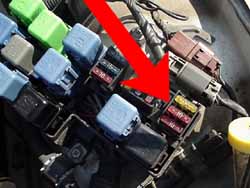
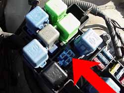
4. Fan relay test: Test the fan relay located on the left front fender,
marked �rad fan�. Do this by turning the headlights on, then off, to prove
the headlight relay is good. Then swap the fan relay with a headlight relay
marked headlight lh (or rh). Check headlights again. If they
work normally, the fan relay is good. The fan relay is in the front fuse
block, shown relay out (5.).
If the fan relay proves bad, repeat step 3, Circuit test, with the good
headlight relay in the fan relay position.
If the fan still does not run, go to step 5, Power supply test
If the fan now runs, its time for a new relay. Install the relay and
you can repeat step 2, System check, or step 3, Circuit test, to prove
the cure.
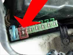
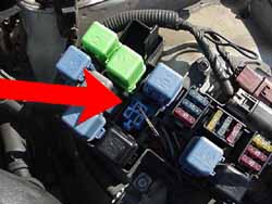
5. Power supply test: Test power supply to relay box with a voltmeter.
Remove �rad fan� relay. With ignition on, check for battery voltage at
the 2 terminals which face the headlight on the driver's side by placing
the black probe on any ground, then checking each terminal with the red
probe (6.).
Note: A test light can be substituted for the voltmeter by clipping
the lead to ground and then touching each terminal with the probe. The
test light brightness level should be similar what you see with a battery
test. Use of a high impedance digital volt-ohmeter provides safety factors
not present in a test light. It is possible that a test light probe
in the wrong place could cause damage where the ohmeter would not. Use
caution.
If the terminals both test good, go to step 5.a, Fan/Harness test
If the either or both terminals test bad, check 10 amp fuse marked �air
cond� on relay box cover and check fusible link marked �rad fan� in the
box directly in front of the battery. (see pics in step 1, Observations)
5a. Fan/Harness test: Check fan operation by placing a jumper across
the two relay terminals closest together. Expect light sparks at
the jumper when contact is first made; this should be providing direct
battery power to the fan.
If the fan runs then reinstall the relay and repeat step 3, Circuit
test. If there is voltage at both relay terminals, a good relay, and a
good fan /harness, then the fan should have worked under step 3, Circuit
test.
If fan does not come on, check harness connector at fan (remove, clean,
reinstall) and re-test. If the fan still does not come on, test the motor
directly. This will require a pair of jumpers directly from the fan connector
(fan side) to the battery. Make the connections to the fan first, then
the battery. Expect light sparks at the moment of connection.
If the fan still does not run, fan replacement is required. Replace
and repeat step 3, Circuit test.
If the fan does run there is a wiring harness issue between the relay
and the fan connector that may require a shop manual, special tools or
professional assistance to find and repair. This is not covered on this
page because of its rarity.
Note: Monitor the condition of the fuse and/or the fusible link that
was replaced for a period of days after getting the system restored. If
they fail again, there is a problem in the wiring or components that may
require a shop manual, special tools or professional assistance to find
and repair. This is not covered on this page because of it's potential
complexity. Never use a larger rated fuse or link to solve the problem;
to do so is a fire hazard.
6. Temp sensor test: If step 3, Circuit test, causes the fan to run,
the only circuit item not checked is the temp sensor (4.). Test
the sensor by measuring its resistance with an Ohm meter when the engine
is cold and then again hot. Readings should be between 2 to 3 K-ohms
cold (68 degrees F ) and .30 to .33 K-ohms at 176 degrees F (~ normal
temp).
If the sensor tests bad, replace and repeat step 2, System check, to
prove the cure.
If the sensor tests good, make sure the terminal connections are clean
and make good contact, then repeat step 2, System check, to prove the cure.
Conclusion:
At first reading, these procedures may seem overly involved. But
taken step by step, they will provide a system check that will give you
the peace of mind of knowing that the fan will indeed work when needed.
A properly operating electric fan provides a certain degree of protection.
It helps keep high cooling system temperatures under control whether the
cause is related to extreme operating conditions or other weaknesses in
the cooling system. Knowing the system is operating as it is designed is
the objective of this exercise.
DISCLAIMER: If while following these procedures, you cause damage to equipment or personnel, it's your fault not ours. They work, we've tried it. But we can't control what you do, so be careful.
Text & testing a collaboration of Buzz
& Toyluvr; Photos by got rice?
of GRacing
Back to TECH |