| Message |
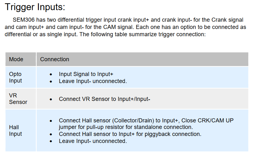
1.) The TT ecu has two connections to the fuel pump control unit (pin 104 - Fuel Pump Control, and pin 35 - Fuel Pump Control (TT)). Reading this wiki page, it seems like the controller wants analog signils (6V for low, 7V for medium, and 12V for high speed). I could also interpret that the voltage transformation is done in the control unit and it needs a digital signal from the ECU to know when to trigger. How did others hook this up to their aftermarket ECU's? if analog, is there a significant current draw? 2.) I plan to eliminate the Idle air regulatior and FICD, and only retain the AAC valve for idle control. I will be using pressure/density control. Are there any trouble points with this strategy that I am not thinking of? 3.) Can I please get an explanation on the difference between pins 51, 52 (CAS Position and CAS reference) and 41, 42 (CAS position -, CAS position +)? Googling, it seems like one pair pulses ever 1°, the other every 120°. Is an aftermarket ECU likely to need one or both? also, I have found conflicting information on whether 41,51 is a pair, or 41, 42, etc. Does anyone know for sure? Here is some info from the ECU, My intuition is to connect Crank-/Crank+ to the 1° differential pair (ie: VR sensor in the chart) and leave the 120° unconnected. Is this wrong? 
 |
 |

