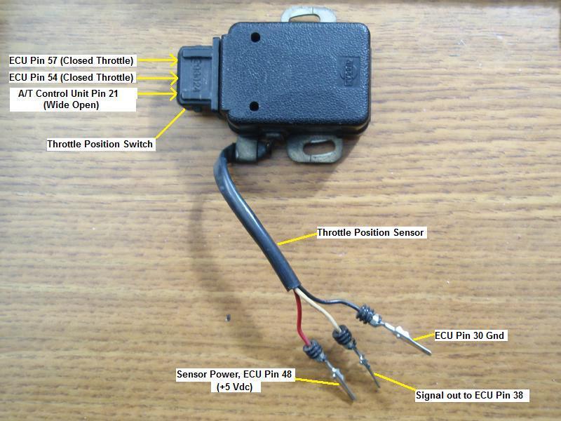
| One of my on-going projects that I'm building is an ECU breakout box for testing ECUs and simulating sensors and other things. For this I needed the functionality of a TPS sensor. Since the TPS sensor also has two switches inside of it I was unable to use a common potentiometer to simulate a working TPS. I had to use a real TPS but I needed a way to control it so I added a shaft that I could connect a knob to. After studying a TPS sensor and how it operates I put together this TPS info. 
The TPS has two switches in it that are made out of relay like contacts. One is for Closed Throttle and the other is for Wide Open Throttle. The Wide Open Throttle switch is only used in cars with an automatic transmission. It's used to send a signal to the A/T control unit.

The FSM says the TPS voltage should be between .4 and .5 volts when the throttle valve is fully closed.

With the TPS sensor that I used, I found that the throttle closed switch was just on the verge of opening when I set the voltage to .46 volts. Not much more than this will cause the switch to open so I suggest keeping the voltage to between .4 and .46 volts.
 The FSM also shows a simulated screen picture of the TPS voltage under test using a Consult test set. That picture shows the voltage set at .46 volts.
 There is also a good picture showing the internals of the TPS, its connections and how its output voltage correlates to the throttle valve opening angle.
 In this close-up picture, look at the closed switch on the right and the wide open switch on the left. When I think of wide open, I think of the throttle fully depressed. But as you can see in this picture, the slot for the wide open switch which rotates clockwise when depressing the throttle causes the switch to engage much sooner than when the throttle is fully depressed.
 Here is a schematic picture showing the connection of the TPS throttle switches to the ECU and A/T control unit.

The TPS sensor can be ohm tested.
(Out of the car)
With the sensor unplugged you should have a resistance (as you rotate the control) of .4 ohm to 9.5k ohm (give or take) when checking the resistance between the center pin and either side of the three sensor leads.
(In the car)
As stated in the FSM, the TPS sensor is approximately 1k ohm when the throttle is released (that's after you've made the voltage adjustment) and approximately 9k ohm when the throttle is completely depressed. Here are some pictures I made while I was making the shaft to be used to control the TPS sensor. It's adhered to the vairiable control with high strength epoxy.


 www.mytwinturbo.com Nissan Data Voice - The first Nissan diagnostic software with a voice!
 Nissan Data Voice on YouTube Download my Nissan 300ZX Vin/Model Lookup. |

