| I've had tons of request for the pictures related to my CAS maintenance write-up so I felt it was time for a new one. The links to the pictures in the first write-up are dead now. In this write-up I will explain more of the operation of the CAS and a little on testing it. First, the internal electrical operation of the CAS does use LEDs (light emitting diodes) and photo diodes as part of the wave forming circuit. This info can be found on page EF & EC-14 in a 1990 FSM. There is also a good picture of the disc (as it is refered to in this writeup). The manual names the disc as the rotor plate. The rotor plate has 360 slots (or slits as is stated in the FSM) for 1 degree signals and six slots (or slits) for the 120 degree signals. When the rotor plate rotates it rotates between LEDs and photo receiver diodes. Although the manual states that the slits continually cut the light being transmitted from the LEDs to the photo diodes, since slits are actually holes, what is happening is that the slits are allowing the light from the LEDs to the photo diodes. Definitions of slits and slots both say they are holes so I'm sure the explaination in the FSM was a mistake of what is actually happening. The circuitry within the CAS converts the light pulses into on and off electrical signals. Now, on to the testing and operation.
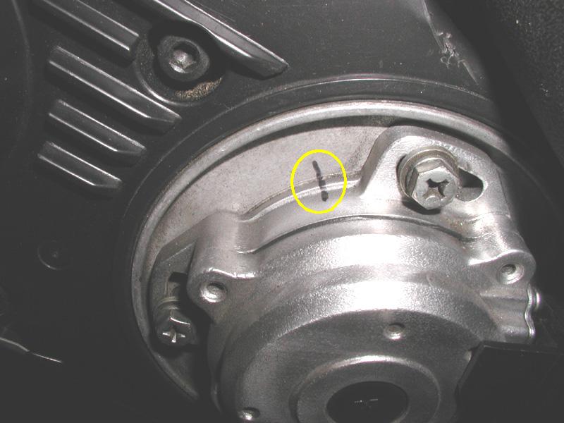
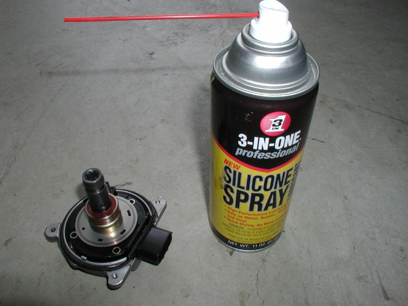
When testing the voltages coming from the CAS you will see a difference in how the 5v pulses are presented depending on which pins you test. While the CAS is mounted and your engine is running, accurate reading of the pulses can only be seen using a test instrument such as an oscilloscope. To test the CAS by hand, pull the CAS and test it with the the harness connected. Have the ignition turned to the ON position. First find ground which will be a pin to one of the far sides of the connector. The pins then are, 4 which is the ground, 3 to battery positive after going through a fusible link and the ECCS relay (when the ignition is on), pin 2 is the 120 degree signal which goes to ECU pins 52 and 42. Pin 1 is the 1 degree signal which goes to ECU pins 51 and 41. With your test leads connected between pin 1 and ground or between pin 2 and ground you will see a 5v pulse when you turn the CAS shaft by hand. Turn it counter-clockwise. This is the way it turns when mounted although it will actually be turning clockwise. Pin 1 and ground will give a pretty fast and constant pulse because there are 360 1 degree slots on the rotor plate and they are spaced very close together (see pictures) and evenly all around the disc. You will see that it takes a longer time to read between each pulse of the 120 degree signal because the slots for those are spaced farther apart (again, see pictures). Also, each one of the pulses for the 120 degree signals will have different lengths of time (the time that 5 volts is displayed) due to each of the 120 degree slots being slightly wider than the other. This can also be seen in the pictures. The widest slot is for cylinder number 1 and the smallest slot is for cylinder number 6. The basic things that indicate a possible bad CAS are a rough running engine, a misfire and the engine being either hard to start or not starting at all. The problem I had was that the engine would start when cold and seemed to run ok but when it warmed up it ran real rough and was almost impossible to start after you shut the engine off. Also, when driving, the car had very little power and would not reach much more than 2500 to 3000 RPMs. The rest of this new write-up is basically the same as I post before except this time the picture links are good. On to the maintenance. Warning: Please read this complete procedure before attempting any repair or maintenance on the CAS. The first thing to do is mark the position of your CAS before you remove it from your motor. You can do this by marking it with a sharpie as I did in the picture below but it is probably better to scribe the metal. If you are planning to adjust the timing then anything that will get you close will do. It is not necessary to disconnect your battery when disconnecting the CAS as all power is removed from the CAS when the engine is turned off. Disconnect the connector to the CAS and remove the three 10mm screws from the slotted holes. When you attempt to pull the CAS out it may feel like a spring is pulling it back in. This is normal and is due to a suction force created by a vacuum space between the cam shaft and the internal shaft of the CAS by lubricating grease. If this happens just pull real hard until it pops out.
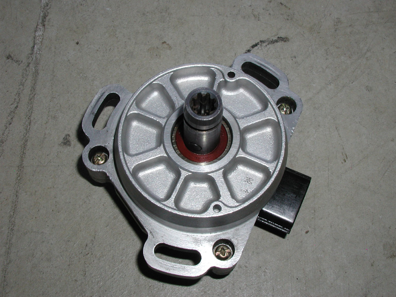
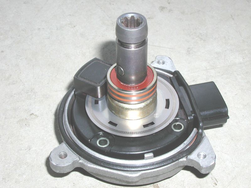
 Once removed sit it down with the shaft pointing up as in the picture below. In this position we will call the two halves the upper and lower. Using a number 2 Philips head screw driver remove the three short Philips head screws that hold the CAS together. Use a small flat tip screw driver and working around the CAS pry the two halves apart.
 Once the two halves have been separated you will see a rubber seal which goes around the CAS and around the connector. DO NOT attempt to remove the rubber seal from around the connector. It is OK to lift the rubber seal from around the CAS to clean the area around it. The picture below is how the CAS should look once the two halves have been separated (this picture is of a partially cleaned CAS).
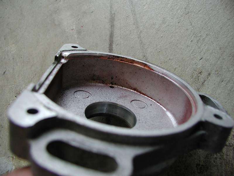
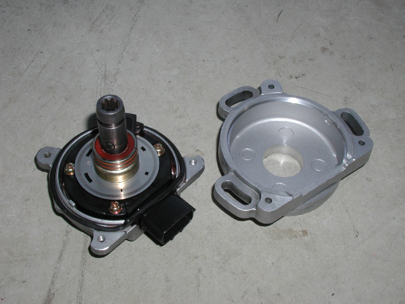 There are two bearings that suspend the internal components within the housing. One is on the shaft that fits into the hole of the upper half and one is pressed into a recessed area on the lower half. The internals are held in place by three long Philips head screws. It is not necessary to remove these screws. If you do remove these screws you will find that you can not separate the internal components from the lower half without the possibility of damaging the CAS due to the lower bearing being pressed into the lower half. Leave the internals attached to the lower half for the rest of this procedure. In the picture below of the upper housing you can see a brownish dust which is dry debris from the breakdown of the sealed bearings which escapes between the bearing casing and the shaft.
 Thoroughly clean the housing using a silicone lubricant such as the type in the picture below. DO NOT use WD40. WD40 contains solvents which will break down the lubricants which are needed to insure continuous operation of the CAS bearings.
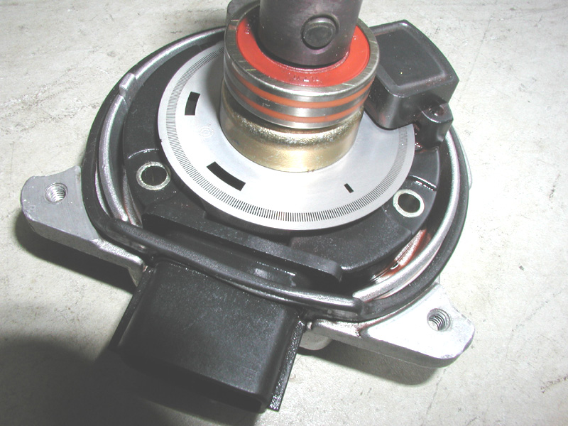
 I will explain some things in this next picture below. The connector to the CAS is a part of the complete molded interior plastic piece (in my picture I have removed the three long Philips head screws from this piece). If you have a CAS with a broken connector it can not be repaired by swapping a connector from another CAS. The CAS operates by photo electric sensors. There are transmitters and receivers which are in the upper and lower portions of the raised square (to the left in this picture) which is a part of the complete molded plastic piece which is also a part of the CAS connector (to the right). There is a steel disc which has a series of continuous small holes around the outside edge and six different size holes toward the inside of the disc. When the disc rotates through the square which contains the sensors, light from the transmitters pass through the holes to the receiver sensors on the opposite side and send pulses to the ECU to initiate the process of triggering both the injectors and the firing the coil packs. The holes in this disc can become covered in debris causing disruptions in the signals being sent to the ECU. The disc in this picture was covered in the dry dusty brownish debris as seen above in the upper housing picture before I cleaned it.
 In the picture below you can see the brownish debris in the bottom of the lower housing. To clean and lubricate the inside area of the lower housing spray a good amount of silicone spray between the small opening around the internals and lower housing until the lower housing is literally full of silicone spray liquid. Rotate the shaft a few times and then drain the liquid onto a rag. Repeat as many times as it takes until all signs of debris are gone and the liquid comes out clean. Spray a small amount of silicone spray between the top of the upper bearing and shaft and again rotate the shaft a few times. Lay the housing on a rag so that the top of the shaft is pointing down toward the floor at an angle and let it sit for a few minutes to allow as much liquid as possible to drain from the housing. When doing this place it in a position where the square piece which contains the sensors is toward the top to help keep liquid away from the sensor area. Once that is done apply one or two drops of 10w30 motor oil to the top of the upper bearing between the bearing and shaft and wipe dry.
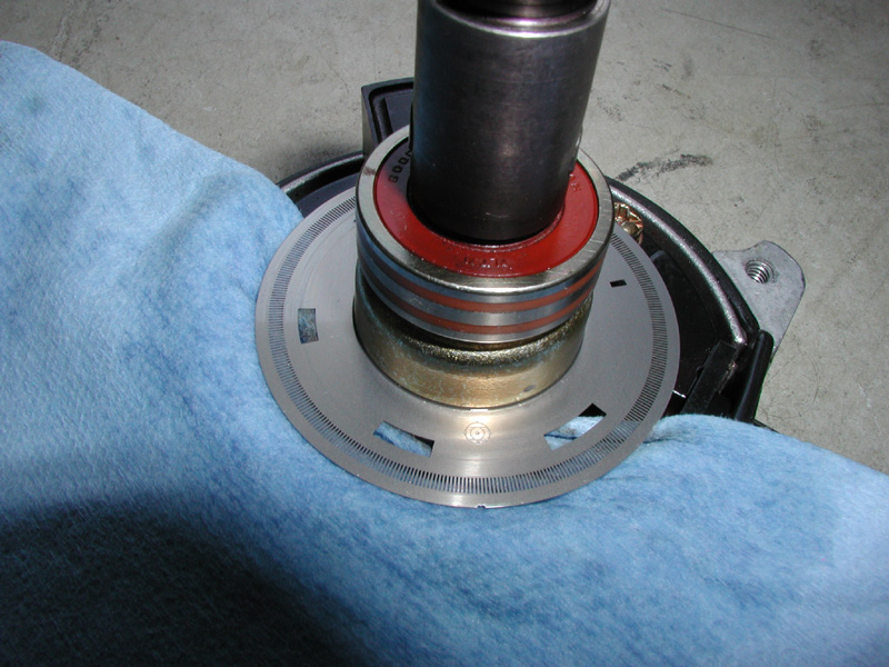
 In the picture below I used a shop towel soaked with silicone lubricant and slipped it under the disc and applied a small amount of downward pressure to the disc while rotating the shaft to clean the under side of the disc. Then I used a dry shop towel to remove any excess lubricant. In this picture you can see one of two cuts in the very outside edge of the disc. This is not damage. This is the way it was manufactured. If you look close (in reality) you can see it is a machine square cut on opposite sides of the disc.
 Once the CAS has been cleaned, reassemble it, reinstall it to the motor and reconnect the connector to the CAS. Cleaning the CAS is very simple. This preventive maintenance procedure will certainly help prolong the life of your CAS and help to keep your Z running smooth.
 www.mytwinturbo.com Nissan Data Voice - The first Nissan diagnostic software with a voice! Download my Nissan 300ZX Vin/Model Lookup. Watch an ECZA meet caravan! |


 New CAS maintenance and testing info. -