There has been some “discussion” about the dual ram air intakes like I installed on my 300ZX.
So to help "clear the air", I will at least attempt to explain the reasons for choosing this configuration.As a starting point, the Z32’s stock air box is very restrictive (that’s a given), however, something else to consider is where the air actually enters the air box.
The air actually enters the system from the underside of the front fenders, and is ducted at least 2 feet before the air actually reaches the air-box! The Z32 utilizes a “Hot Wire” style Mass Air Flow (MAF) to determine the amount of air entering the engine.
As air passes over the wire, the wire is cooled.
Circuitry within the MAF adjusts the voltage to maintain the resistance of the wire (and therefore temperature of the wire).
This voltage signal is sent to the ECU to balance and deliver the correct amount of fuel to the engine.
The signal voltage range for the Z32 MAF is 0.500 to 5.12 VDC.
Also incorporated within the housing and circuitry is ambient temperature sensor.
Algorithms adjust the signal voltage to compensate for changes in air temperature sent to the ECU. The MAF is used in conjunction with an oxygen sensor, which allows the engine's air/fuel ratio to be controlled very accurately.
The MAF sensor provides the open-loop controller predicted air flow information (the measured air flow) to the ECU, and the oxygen sensor provides closed-loop feedback in order to make minor corrections to the predicted air mass.
Of important note is the MAF does not measure Air Pressure, only the amount of air mass flowing over the “Hot Wire” cooling the wire. In the OEM system, air enters ducting from the underside of each front fender, is ducted to the filter housing, passes thru the MAF, then splits to each turbo inlet.
By design, the whole system is very restrictive!
Nissan engineers did this primarily to reduce noise (other reasons as well, but beyond the scope of this discussion). Back in the late 60’s and early 70’s, OEMs found that by placing the air intake in the front airstream created “Ram Air” effect (1969 Ram Air Firebird, 1964 Ford Thunderbolt are prime examples) which resulted in significant mid-range horsepower and torque gains.
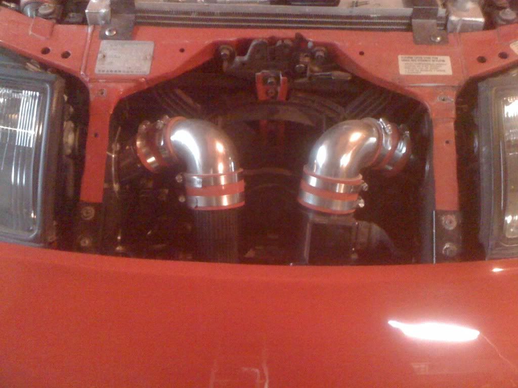
Noteworty is that GM placed their Ram Air Intakes under the front bumper, while Ford removed the inner headlights and ducted the air cleaner housing to these openings. When the stock Z32 inlet system is removed, the dual air intakes significantly increase inlet airflow.
Usually, only 1 MAF sensor is utilized measuring the airflow on one side (as provided by Z1’s kit).
In the Single MAF configuration, the thought is whatever the monitored side is doing, the un-monitored side is doing the same.
There are a number of “piggy back” systems available that utilize 2 MAF’s to measure airflow in both sides, but I’ll reserve comment for later discussion of the pros and cons of single vs. dual MAF systems as it is beyond the scope of this discussion subject.
Upgrading (actually re-programming) the ECU is required due to these significant increases in airflow over the stock system.
This is usually best accomplished by editing the fuel and ignition mapping on a dynamometer. How to accommodate the fuel and ignition mapping for Ram Air?
Obviously the dynamometer will not allow the tuner to adjust the fuel and ignition mapping while the vehicle is stationary.
This is where the tuner’s experience and expertise comes into play.
After tuning for best power output on the dyno, the tuner should then test drive the vehicle while monitoring the O2 sensors.
He (or she) will then modify the mapping to accommodate for the Ram Air effect(s), ensuring that the fuel mapping is on the rich (or fat) side for insurance. There is some concern that the current flow metering systems for the Z32 are not designed to accommodate ram pressure therefore making ECU scheduling inaccurate and unreliable. The Z32 MAF does not measure Air Pressure, only Mass Air Flow.
By placing the Intake opening(s) for Ram Air, there will be significant increases in Air flow at speed.
However, the differences in Air Pressure are negligible, as the intake tract is usually under a vacuum condition, caused by the air demand of the engine and turbochargers. Remember that the O2 sensor(s) are constantly monitoring the exhaust flow, and relaying that information to the ECU for adjustment (closed loop system).
I recognize that a system could be made which accounts for the Ram Air pressure and which could probably benefit power output.
But how much a system would yield and how much time and $$ to develop?
Testing of this system thus far has not revealed any negative effects to date so probably not worth the undertaking.
Again I should point out the MAF only measures air flow mass, NOT pressure.
While conceivable that Ram Air would increase the air pressure in the inlet, the MAF is able to accommodate the change in the amount of additional air flowing into the engine. A comment was made that there would be a 5-10 hp loss, due to the additional length of ducting.
When compared to the OEM system, the ducting is actually shorter and has a larger cross-sectional area than the OEM system. If you install the Z1 Motorsports Dual Air Intake system, below the center “grill” panel, you would install 2 90 degree cast aluminum elbows, the MAF sensor, MAF adapter and Air-filters (single MAF set-up). If you choose to move your air filters into the Ram Air configuration, (as I have) you will need 11 inches of 3.10” OD ducting for the R/H side and 4 inches for the LH side, and the addition of a 45 degree elbow for each side.
These are the only additional lengths required to bring both air filters from below the center “grill” panel to the front radiator opening. To calculate the additional drag (caused by the increased duct lengths) is first accomplished using the following formula (Reference AIAA Design Engineer’s Guide Copyright 1983, Page 7-5):
NR=pVd/µ
Where Reynolds Number =
p = density of the fluid (air)=0.023769 Ft3 (AIAA Design Engineer’s Guide Copyright 1983, Page 7-4)
V= mean velocity of the fluid=88.5 fps or 60mph
d= Inside diameter of duct=3.000 in or 0.25 ft
µ= viscosity of the fluid (air)=3.83649E-7 s/Ft2 or 0.000000384 ft2
RN=1369503 Use the above Reynolds Number to find the Friction Factor on the Moody Chart:
[ http://upload.wikimedia.org/wikipedia/commons/8/80/Moody_diagram.jpg ] The chart yields a 0.0115 Friction Factor... As you can see any additional length in ducting, even at a airflow rate of 60 mph, the Friction factor is negligible. (hardly worth taking the time to finish the rest of the flow calculations). If you do some algebraic maneuvering, to add the duct length your equation is:
RNl= pV^2L^2 / µVL
RNl=5021693.343
The Reynolds Number (length) is off my CD chart, the difference is so small other factors such as air temperature have a bigger impact to the flow calculations. So adding length to the inlet ducting to position the air filters for ram air, the difference is so small, it’s not worth calculating. Where the 5-10 horsepower difference came from is anyone’s guess and obviously not calculated. The last areas of comment were the ingestion of water thru the system.
If water passes through the filters, and manages to finally make it into the combustion chamber, the effect is a slight reduction in power.
In the early 90’s many companies were marketing water injection units to reduce detonation.
Some of these units actually were pretty sophisticated units (considering the state of the art at that time), and utilized a detonation sensor to activate the system.
I installed one of these systems on a 340 Six Pack Barracuda, that had the Mopar Performance 11 second engine parts package installed.
This allowed me to run pump gas without hurting the engine. When driving my 300ZX back from Z Sports in Everett, WA, after passing emissions testing, I encountered some pretty heavy rain (Go Figure, I live in Seattle!).
The drive took about 45 minutes due to “rush hour”.
If any rain had been ingested during the drive, I couldn’t feel any effect what-so-ever. Several days later I did notice two small, 2 inch “puddles” under the front wing below each air filter. I removed each and visually inspected the filters and ducts. I reinstalled them as the filters and ducts showed no damage, dirt or any foreign objects. Obviously the engine was ingesting some amount of filtered water, how much is an unknown at this point, however the amount that was ingested did not affect performance in any way. Also of note is to consider drag boats and their operating environment.
Their supercharged engines ingest huge amounts of water on every run... So it would be logical to assume, that considering OEMs have marketed High Performance Vehicles utilizing Ram Air, there are systems that inject water into the intake tract to control detonation, and the fact that High Performance Drag Boats ingest huge amounts of water without hurting performance, pretty much rules out any harm that could occur when driving in the rain and may have some beneficial effects as well.
One of the biggest reasons why I choose to configure my ram air, was that I hated the way the filters were mounted under the center panel.
There just wasn’t a clean way to provide mounting supports for the air filters.
I did not like the fact that the only things supporting the filters were the hose clamps at each joint.
By using the Ram Air configuration, this allowed the air filters to be mounted parallel (or close to it), greatly simplifying the installation, and making it much easier for maintenance.
 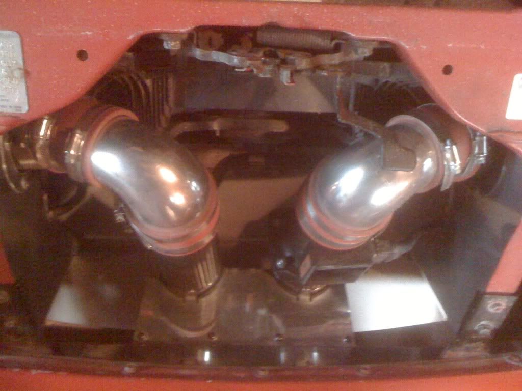
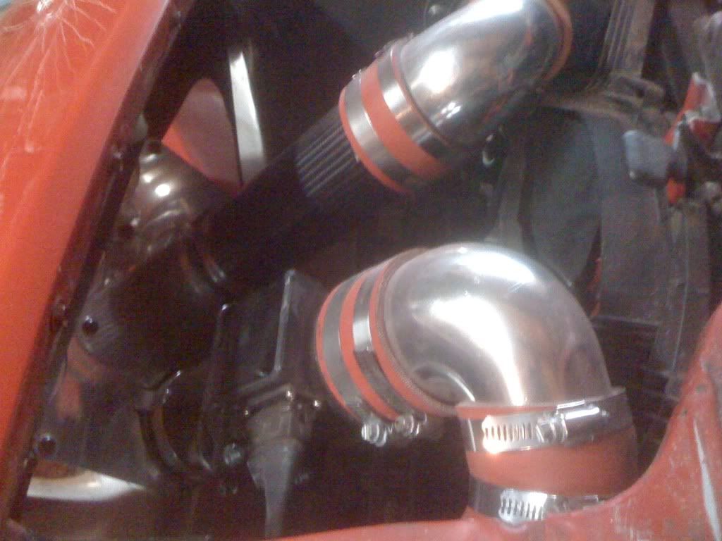
Also by fabricating custom brackets, each segment of the system is supported, which does not rely upon the hose clamps sealing the joint to support the ducts and filters.
Also of note is that by fabricating the custom ducts, I paid particular attention to all of the joints.
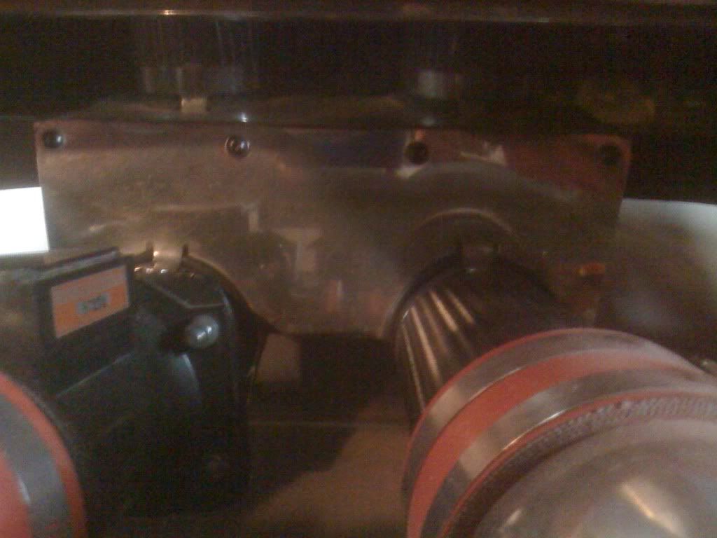
Now, all of the joints are smooth and do not have any steps that could interfere with air flow. Here’s a photo of the tool I developed to fabricate the ducts with.
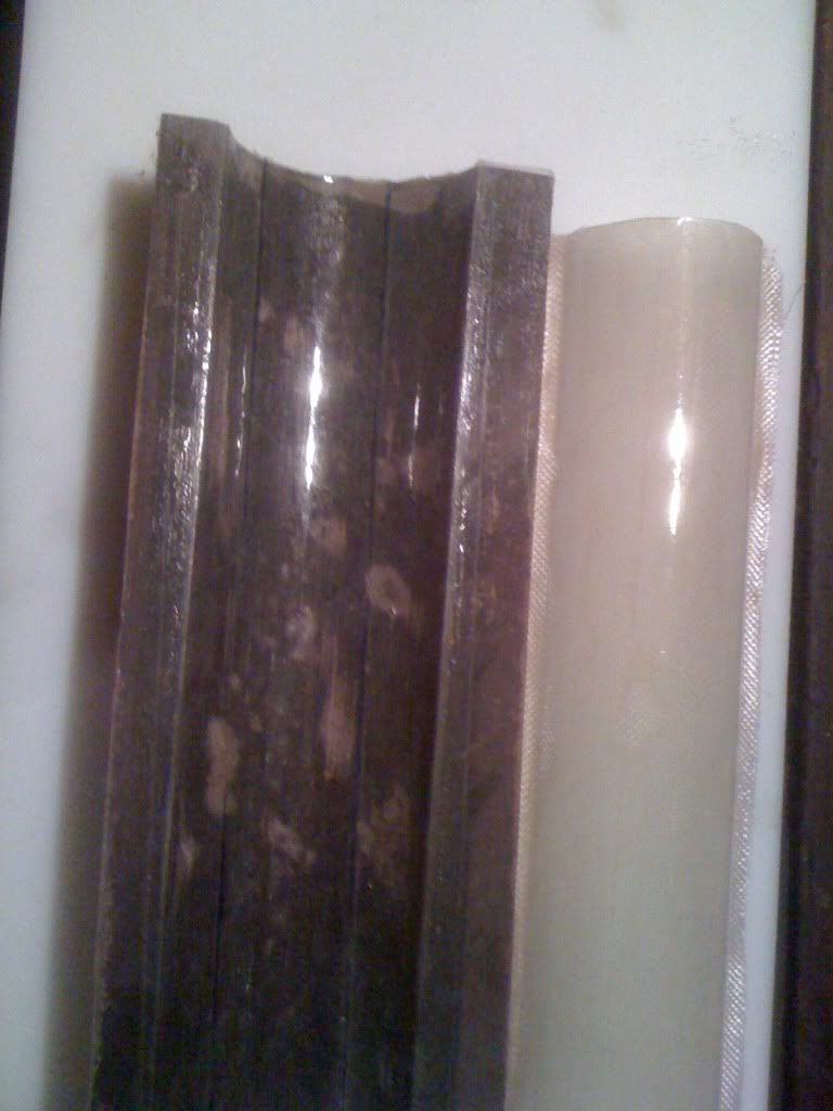
To the Right of the tool is a “test” part I made using fiberglass (proof of concept). The CF Ducts were laid up in halves 3 or 4 plies at a time, then consolidated to make a round duct 14 plies thick. In closing, I had good engineering reasons to use a Ram Air Configuration, is well executed, and enhances performance.
It may not be your "cup of tea" for your 300ZX, but hopefully you now understand the reasons for choosing this configuration. Also noteworthy is that I did consider using a NACA Duct vented center grill panel.
It could be done by building an airbox below it, however maintenence would be much more difficult and time consuming,
And probably would not provide as much Ram Air as the system I developed, however, may warrant some additional thought... The thing that I like the best about my system?
You can actually hear the noise of the air rushing into the turbos...
|


 S2z's Ram Air... -